Power generation system and power generation method for supplying power to power grid

A power generation system and grid power supply technology, applied in the field of electric power, can solve the problem that thermal power units and energy storage subsystem 1 cannot operate in conjunction, the utilization rate of energy storage subsystem 1 is reduced, and the joint operation time of energy storage subsystem 1 and generator set 2 is long. problems such as shortening

Active Publication Date: 2017-12-08
北京睿能世纪科技有限公司
View PDF5 Cites 2 Cited by
  • Summary
  • Abstract
  • Description
  • Claims
  • Application Information

AI Technical Summary

Problems solved by technology

[0004] On the one hand, the thermal power unit needs to be maintained and overhauled once a year, and each maintenance and overhaul takes two to six weeks. In this way, when the thermal power unit is being maintained and overhauled, both the thermal power unit and the energy storage subsystem 1 are obviously cannot run jointly
[0005] On the other hand, when some components in the thermal power unit, such as boilers or steam turbines, etc. break down, these components need to be repaired, and the time required for the maintenance operation is generally longer. In the process of implementing the maintenance operation, the thermal power unit and energy storage subsystem 1 obviously cannot work together
[0006] Obviously, the above reasons will greatly shorten the joint operation time of the energy storage subsystem 1 and the generator set 2, so that the utilization rate of the energy storage subsystem 1 will also be greatly reduced

Method used


Image

  • Power generation system and power generation method for supplying power to power grid
  • Power generation system and power generation method for supplying power to power grid
  • Power generation system and power generation method for supplying power to power grid

Examples


Embodiment Construction

[0043] The following will clearly and completely describe the technical solutions in the embodiments of the present invention with reference to the accompanying drawings in the embodiments of the present invention. Obviously, the described embodiments are only some, not all, embodiments of the present invention. Based on the embodiments of the present invention, all other embodiments obtained by persons of ordinary skill in the art without making creative efforts belong to the protection scope of the present invention.

[0044] In order to solve the problems existing in the prior art, an embodiment of the present invention provides a power generation system and a power generation method for power grid.

[0045] A power generation system for supplying power to a grid provided by an embodiment of the present invention is firstly introduced below.

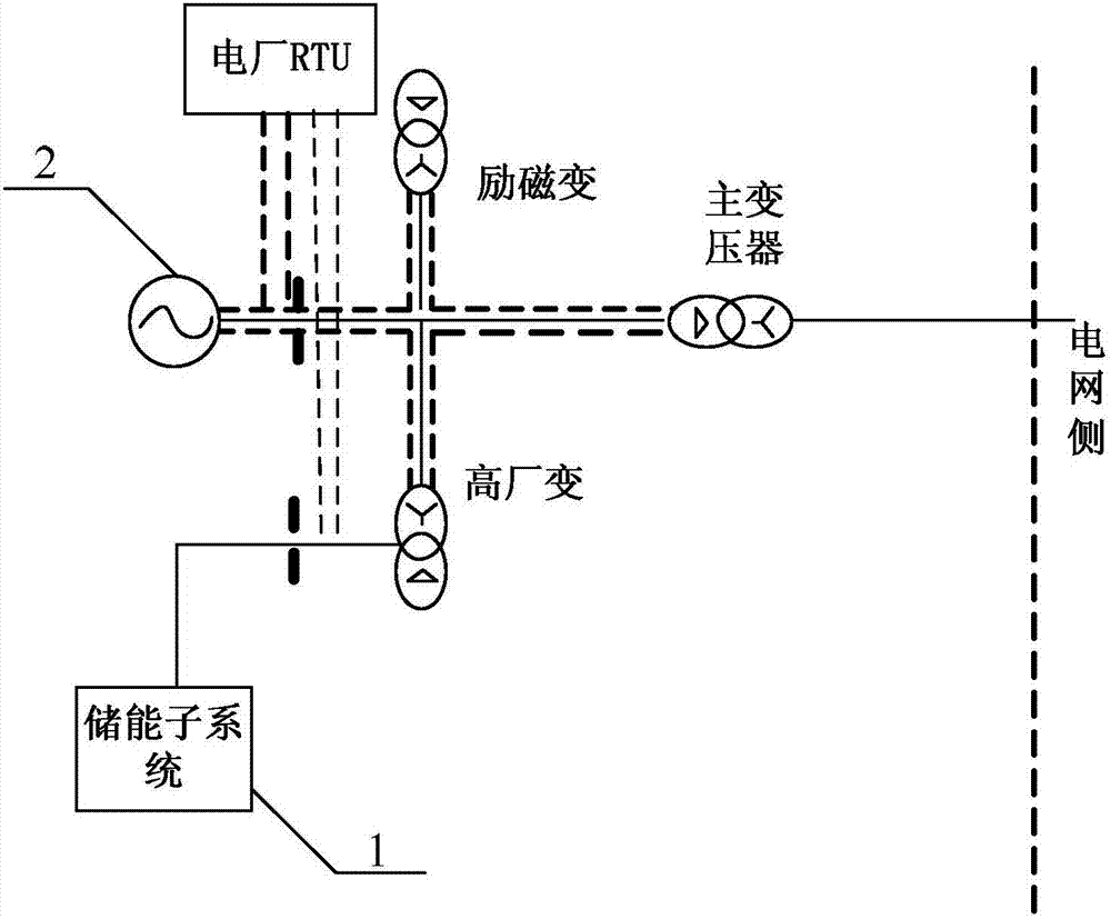
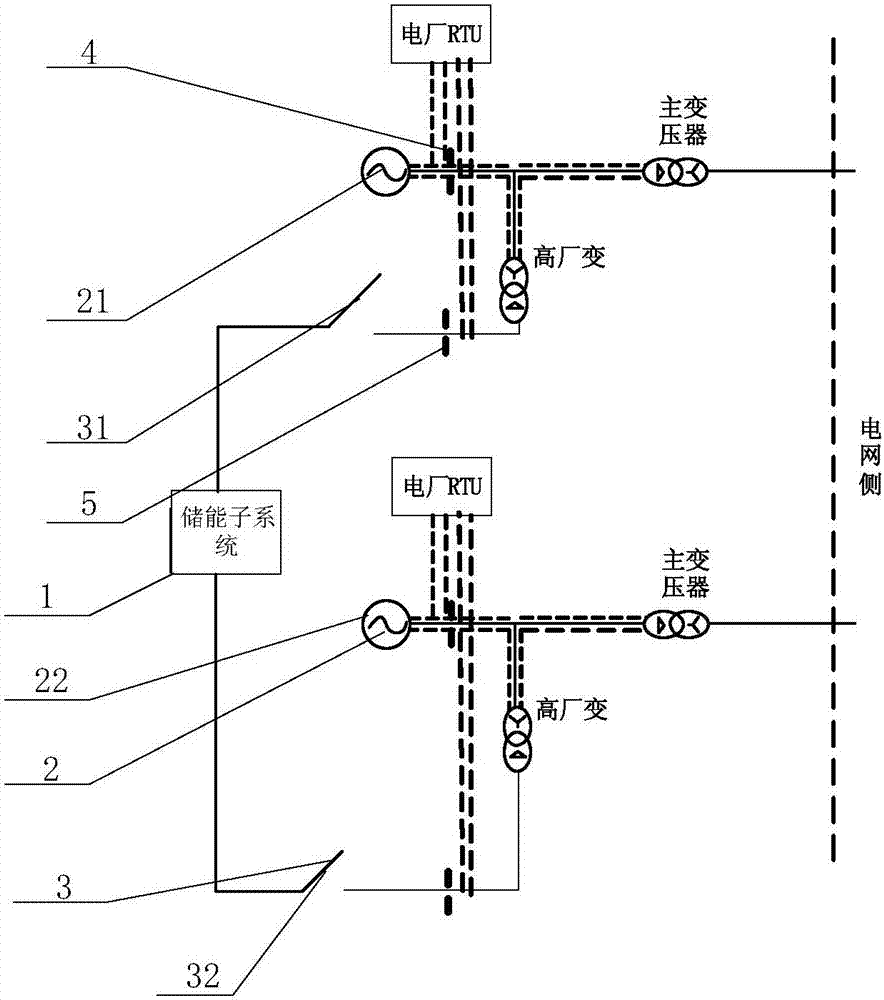
[0046] see figure 2, which shows a schematic structural diagram of a power generation system for power grid provided by an embodim...


PUM


Abstract

The embodiment of the invention provides a power generation system and power generation method for supplying power to a power grid. The power generation system comprises at least two power generator sets and an energy storage sub-system, wherein the at least two power generator sets are connected in parallel and both are electrically connected with the power grid, a control switch is arranged between the energy storage sub-system and a signal output end of each power generator set so as to control connection or disconnection between the energy storage sub-system and the signal output end of the power generator set, and the energy storage sub-system is configured to be in a way that one of the control switches is switched on, the other control switches are switched off, and a compensation power is output by the energy storage sub-system to compensate a difference value between a target output power and an actual output power of the power generator set corresponding to the control switch which is switched on currently. With the power generation system provided by the embodiment of the invention, the combined running time of the energy storage sub-system and the power generator sets can be effectively prolonged, so that the utilization ratio of the energy storage sub-system is greatly improved, and meanwhile, the problem that an error is easy to occur during calculating a plurality of compensation powers also can be reliably prevented.

Description

technical field [0001] The invention relates to the field of electric power technology, in particular to a power generation system and a power generation method for power grids. Background technique [0002] Such as figure 1 As shown, the existing power generation system for supplying power to the grid usually includes: an energy storage subsystem 1 and a generator set 2 connected in parallel with the energy storage subsystem 1. The energy storage subsystem 1 and the generator set 2 can jointly respond to the dispatching instructions of the grid. In order to realize the complementary advantages of the energy storage subsystem 1 and the generator set 2, so as to provide more high-quality and efficient regulation services for the power grid. [0003] In the actual operation process, due to various reasons, the joint operation time of the energy storage subsystem 1 and the generator set 2 is often short. The above reasons will be described below by taking the case where the g...

Claims


Application Information

Patent Timeline
Patent Type & Authority Applications(China)
IPC IPC(8): H02J3/38H02J3/28
CPCH02J3/28H02J3/38
Inventor 薛飞牟镠峰
Owner 北京睿能世纪科技有限公司
Why Eureka
Try Eureka