
Smearing actuator

A technology of actuators and coatings, applied in the direction of architecture and building structure, etc., can solve the problems of inability to complete the application of equipment and limited application scope, and achieve the effect of good application quality and high efficiency

Active Publication Date: 2017-12-08
深圳班翟机器人有限公司
View PDF7 Cites 8 Cited by
  • Summary
  • Abstract
  • Description
  • Claims
  • Application Information

AI Technical Summary

Problems solved by technology

On incomplete planes, such as walls with holes in doors and windows, the existing equipment cannot complete the application, and the application range is very limited

Method used


Image

  • Smearing actuator
  • Smearing actuator
  • Smearing actuator

Examples


Embodiment 1

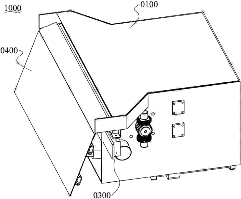
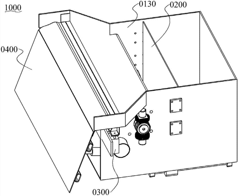
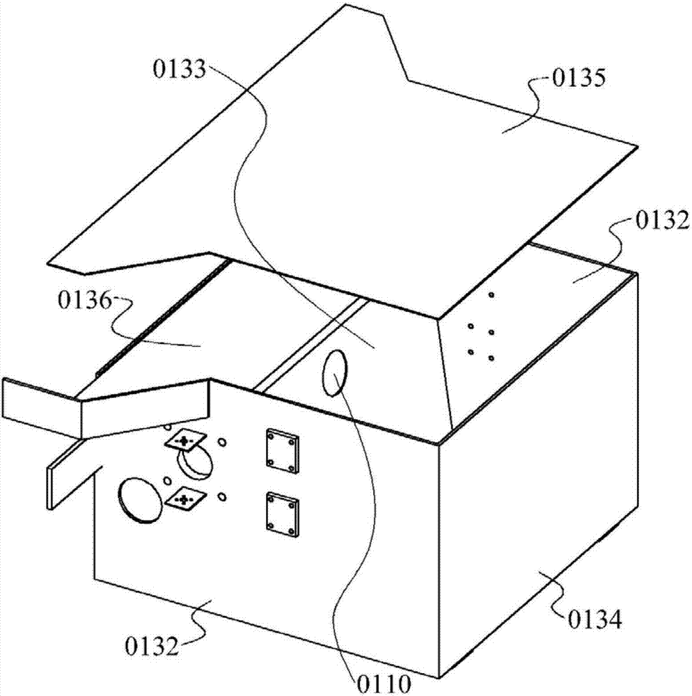
[0043] Please refer to Figure 1~5The smearing actuator 1000 has a material storage unit 0100 for storing paint, and has a material inlet 0110 and a material outlet 0120, the material inlet 0110 is used for inputting paint, and the material outlet 0120 is used for outputting paint.

[0044] Specifically, the storage unit 0100 may adopt structural forms such as a hopper and a box. According to actual needs, the storage unit 0100 can have a closed box structure or an open hopper structure. In this embodiment, the storage unit 0100 has a housing 0130 with a closed box structure, and the housing 0130 has a bottom plate 0131 , side plates 0132 , front sealing plate 0133 , rear sealing plate 0134 and top plate 0135 . Wherein, the front sealing plate 0133 is located in the middle of the bottom plate 0131, surrounded by the bottom plate 0131, side plates 0132, front sealing plate 0133 and rear sealing plate 0134 to form a hopper for containing paint, and is closed from the top by the...

Embodiment 2

[0074] This embodiment and embodiment 1 belong to different implementation modes of the same scheme, and have the same structural layout. Only the differences between the two will be described in detail below, and the similarities will not be repeated.

[0075] see Figure 6~7 , the storage unit 0100 has a housing 0130, the housing 0130 has a side plate 0132, a rear sealing plate 0134 and a top plate 0135, the top plate 0135 is provided with a feed port 0110 for inputting paint, the top plate 0135, the side plate 0132 and the feeding mechanism 0200 surrounds and forms the discharge port 0120 for outputting paint.

[0076] The conveying mechanism 0200 includes a conveyor belt 0230. Specifically, the conveyor belt 0230 includes a driving roller, a driven roller, and a conveyor belt 0230 tensioned to connect the driving roller and the driven roller. The conveyor belt 0230 rotates continuously to convey the coating. Wherein, the upper surface of the conveyor belt 0230 is a mater...


PUM


Abstract

A smearing actuator is provided with a storage unit, a control mechanism, a smearing mechanism and a conveying mechanism. The storage unit is used for storing coating and provided with a feeding opening and a discharging opening, the feeding opening is used for inputting the coating, and the discharging opening is used for outputting the coating. The control mechanism is provided with at least one stop portion arranged on the discharging opening, and the stop portions are used for stopping part or all of through-flow faces of the discharging opening. The smearing mechanism is provided with a rotatable smearing plate, the upper end of the smearing plate communicates with the discharging opening, and the smearing plate can rotate in a plumb face around the connecting line of the smearing plate and the discharging opening. The conveying mechanism is used for conveying the coating in the storage unit to the smearing mechanism through the discharging opening. The smearing actuator has the wide application range, extremely high efficiency and good smearing quality.

Description

technical field [0001] The invention belongs to the technical field of engineering machinery, in particular to a smear actuator. Background technique [0002] In the field of architectural technology, smearing is a process of applying paint to the wall to make the paint firmly adhere to the wall to form a smooth and flat surface. The traditional smearing work is mainly undertaken manually, and the workload is heavy. Especially the plastering work needs to be painted and leveled many times, the steps are complicated and the efficiency is very low. [0003] At present, some plastering instruments have appeared to replace traditional manual smearing. These plastering equipment have solved the manpower burden problem to a certain extent, and efficiency has improved to some extent, but there are still some problems. This type of equipment generally adopts a semi-automatic method, and due to structural limitations, it can only be applied to flat walls. On incomplete planes, su...

Claims


Application Information

Patent Timeline
Patent Type & Authority Applications(China)
IPC IPC(8): E04F21/08
CPCE04F21/08Y02E60/10
Inventor 卢贤资吴水传段宁邓胜文
Owner 深圳班翟机器人有限公司
Learn More