
Automobile die with temperature controlling function

A technology for automotive molds and temperature control, applied in the direction of non-rotational vibration suppression, etc., can solve the problems of difficult collection and reuse of melt, gas-liquid mixture equipment pollution, and affecting the quality of molds, so as to achieve high quality, prevent condensation, and reduce heat The effect of the loss

Inactive Publication Date: 2017-12-08
慈溪市现代模具有限公司
View PDF0 Cites 5 Cited by
  • Summary
  • Abstract
  • Description
  • Claims
  • Application Information

AI Technical Summary

Problems solved by technology

[0002] The automobile mold with temperature control function is a special mold used to produce auto parts, which is widely used in automobile production. The existing automobile mold with temperature control function usually includes an upper template and a lower template, and the upper template It is set opposite to the lower template and plugged with each other to form a mold cavity. The positioning of the mold directly affects the quality of the generated mold. How to increase the positioning accuracy of the mold is the first problem to be solved by every mold manufacturer. The lower template moves relatively, and after extrusion, the excess melt is discharged to cool to form auto parts. However, during the extrusion process, it is usually accompanied by the discharge of excess gas, so that the excess melt and gas are sprayed outward. Not only is it difficult to collect and reuse excess melt, resulting in waste, but also the gas-liquid mixture injected is likely to cause pollution to the equipment

Method used


Image

  • Automobile die with temperature controlling function
  • Automobile die with temperature controlling function
  • Automobile die with temperature controlling function

Examples


Embodiment Construction

[0025] Embodiments of the present invention will be described in detail below in conjunction with the accompanying drawings.

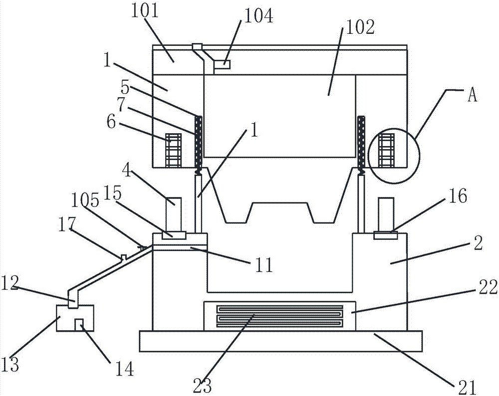
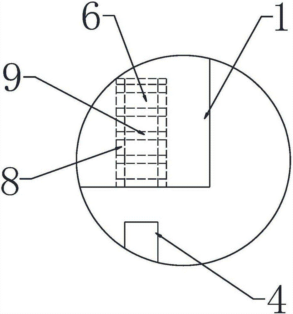
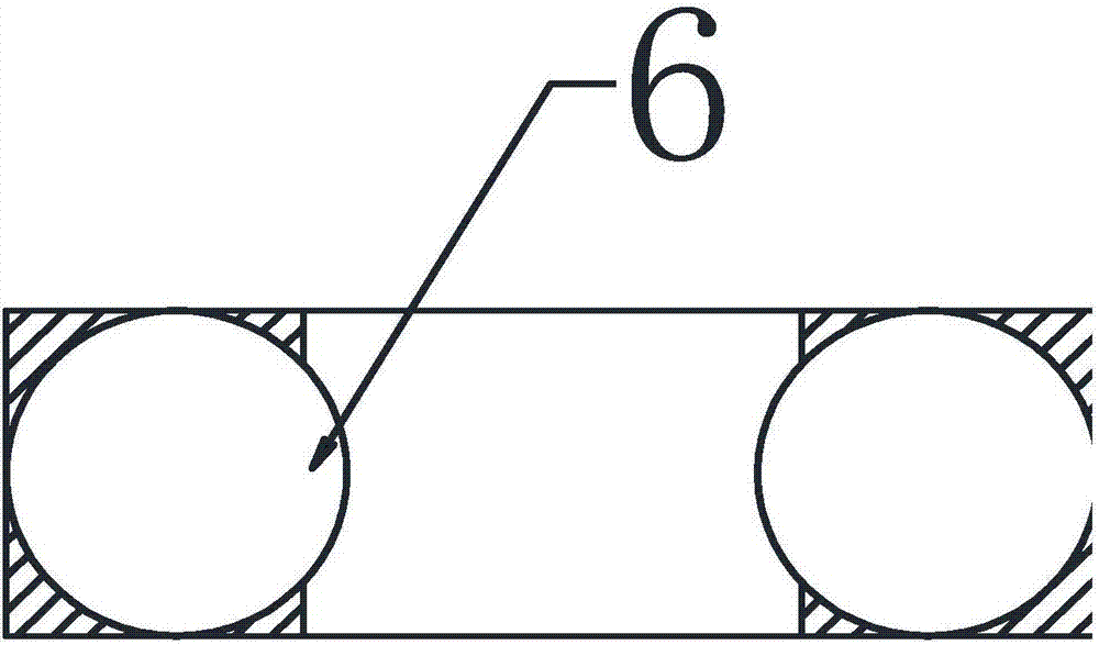
[0026] refer to figure 1 — image 3 , the present invention provides an automobile mold with a temperature control function, comprising an upper template 1 and a lower template 2, the upper template 1 includes an upper mounting seat 101, an upper mold core 102, and the lower template 2 includes a lower mounting seat 21, The lower mold core 22, the upper surface of the upper mounting seat 11 is equipped with an upper top plate, the upper top plate is provided with a sprue, the gate is connected to the feeding channel, and the feeding channel passes through the upper mounting seat 101 is connected with the upper mold core 102; the upper mold core 102 is fixedly installed in the upper mounting seat 101 by bolts; the upper mold core 102 and the lower mold core 22 cooperate with each other to form a molding cavity; the lower mold core 102 Installed on the...


PUM


Abstract

The invention relates to the field of moulds, and provides an automobile mold with a temperature control function, which is more accurate in positioning, produces high-quality automobile parts, and can effectively collect excess melt for repeated use, saving resources; When the lower templates are close to each other, the shock absorbing ring can play a buffer role and prolong the service life of the mold; it can effectively release the gas in the melt to balance the pressure; it can prevent the melt from condensing in the discharge pipe and reduce the liquid storage The loss of heat in the tank saves the energy consumption of the heating device; the temperature of the material in the discharge pipe of the gate is detected in real time, and the temperature controller sends a closing signal to the discharge valve when the detected temperature is lower than the preset temperature to prevent the material in the injection mold from The temperature fails to reach the required temperature value, and the material whose temperature fails to reach the required temperature value is effectively recovered. Only when the detected temperature is higher than or equal to the preset temperature, a signal for entering the mold is sent to the discharge valve, and the material enters the mold. in the molding cavity.

Description

technical field [0001] The invention belongs to the technical field of mold design and manufacture, and in particular relates to an automobile mold with a temperature control function. Background technique [0002] The automobile mold with temperature control function is a special mold used to produce auto parts, which is widely used in automobile production. The existing automobile mold with temperature control function usually includes an upper template and a lower template, and the upper template It is set opposite to the lower template and plugged with each other to form a mold cavity. The positioning of the mold directly affects the quality of the generated mold. How to increase the positioning accuracy of the mold is the first problem to be solved by every mold manufacturer. The lower template moves relatively, and after extrusion, the excess melt is discharged to cool to form auto parts. However, during the extrusion process, it is usually accompanied by the discharge...

Claims


Application Information

Patent Timeline
IPC IPC(8): B29C45/26B29C45/34B29C45/73B29C45/78F16F15/08
CPCB29C45/2602B29C45/2669B29C45/34B29C45/73B29C45/78B29C2045/2671B29C2945/7604B29C2945/76531F16F15/08
Inventor 景伟德
Owner 慈溪市现代模具有限公司
Learn More