
Mechanical arm with precise positioning function

A technology of precise positioning and robotic arm, which is applied in the field of machinery, can solve problems such as complex internal structure, single grasping point plane, limited degree of freedom of mechanical arm, etc., and achieve the effect of improving safety reliability and simple structure

Inactive Publication Date: 2017-12-05
LIUZHOU FUNENG ROBOT DEV CO LTD
View PDF8 Cites 9 Cited by
  • Summary
  • Abstract
  • Description
  • Claims
  • Application Information

AI Technical Summary

Problems solved by technology

[0003] Most of the robotic arms equipped with steering and lifting mechanisms in the prior art have problems such as large volume and complicated internal structure. Because of their huge volume and inflexible operation, it is difficult to complete the grasping work of objects in narrow spaces, and the grasping points The plane is relatively single, and the object cannot be precisely positioned; the mechanical arm with a simple structure has limited degrees of freedom, and has restrictions on the shape and size of the grasped object, which cannot meet the handling and assembly of objects from various angles, and cannot realize the positioning of objects. precise positioning of

Method used


Image

  • Mechanical arm with precise positioning function
  • Mechanical arm with precise positioning function
  • Mechanical arm with precise positioning function

Examples


Embodiment Construction

[0032] The present invention will be described in further detail below in conjunction with the accompanying drawings and embodiments, so that those skilled in the art can implement it with reference to the description.

[0033] It should be understood that terms such as "having", "comprising" and "including" as used herein do not entail the presence or addition of one or more other elements or combinations thereof.

[0034] It should be noted that the experimental methods described in the following embodiments, unless otherwise specified, are conventional methods, and the reagents and materials, unless otherwise specified, can be obtained from commercial sources.

[0035] In the description of the present invention, the terms "transverse", "longitudinal", "upper", "lower", "front", "rear", "left", "right", "vertical", "horizontal", " The orientations or positional relationships indicated by "top", "bottom", "inner", "outer", etc. are based on the orientations or positional rel...


PUM


Abstract

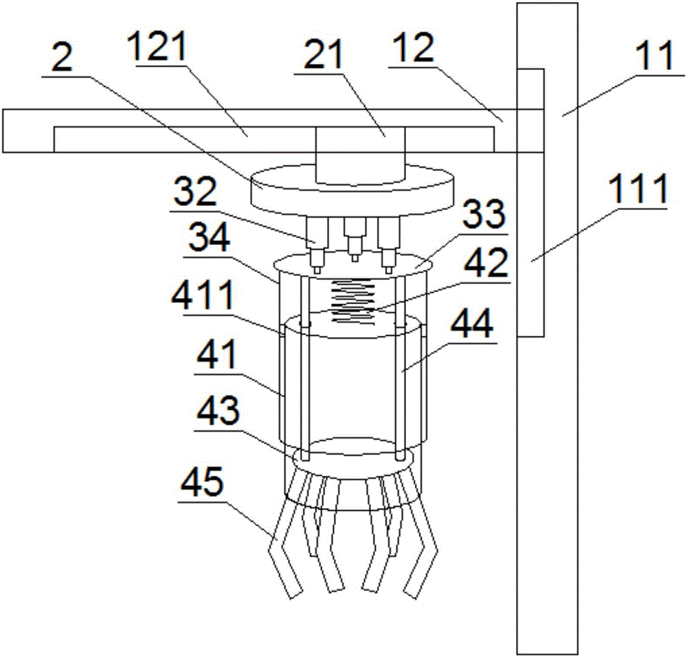
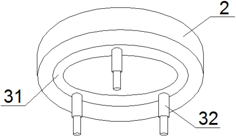
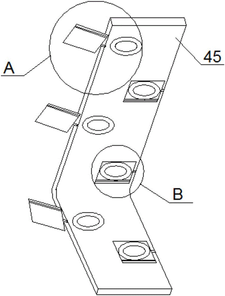
The invention discloses a mechanical arm with a precise positioning function. The mechanical arm comprises a support, a base, an adjusting mechanism, a grabbing mechanism and a plurality of suction mechanisms, wherein the support comprises an upright support body and a cross support body which is horizontally connected to the upright support body in a sliding mode; the base is horizontally connected to the lower portion of the cross support body in a sliding mode, and an annular groove is formed in the lower surface of the base; the adjusting mechanism comprises an annular rotary base, three telescoping rods, a first disc and a sleeve; the grabbing mechanism comprises a cylinder, a compression spring, a second disc, two upright columns and a plurality of claw bodies, the cylinder is sleeved with the sleeve, the compression spring is arranged between the cylinder and the first disc, and a plurality of circular grooves are formed in the lateral side of any one claw body; each suction mechanism is arranged in one circular groove, and any one suction mechanism comprises a suction disc and a sliding plate. In the mechanical arm, when the cross support body moves in the vertical direction, the base moves in the horizontal direction, and the lengths of the three telescoping rods are adjusted, it is achieved that the position where the grabbing point of the grabbing mechanism is located is precisely adjusted in a multidirectional and multi-angle mode; therefore, the precise positioning function of the mechanical arm is achieved.

Description

technical field [0001] The invention relates to the field of mechanical technology. More specifically, the present invention relates to a precisely positioned robotic arm. Background technique [0002] Robotic arms have been widely used in industrial production sites, and can complete tasks such as welding, handling, assembling, and cutting. The use of robotic arms is of great significance to improving production efficiency and product quality, improving the working environment, ensuring human safety, and reducing production costs. [0003] Most of the robotic arms equipped with steering and lifting mechanisms in the prior art have problems such as large volume and complicated internal structure. Because of their huge volume and inflexible operation, it is difficult to complete the grasping work of objects in narrow spaces, and the grasping points The plane is relatively single, and the object cannot be precisely positioned; the mechanical arm with a simple structure has l...

Claims


Application Information

Patent Timeline
IPC IPC(8): B25J9/10
CPCB25J9/10
Inventor 李应煌梁娟
Owner LIUZHOU FUNENG ROBOT DEV CO LTD
Learn More