
Component preparation device

A technology for components and equipment, applied in the field of component supply equipment, can solve the problems of long cycle, being between the board and the camera, adverse effects on the reliability of structural components, etc., and achieve the effect of preventing pollution

Active Publication Date: 2017-12-01
STIWA HLDG
View PDF7 Cites 1 Cited by
  • Summary
  • Abstract
  • Description
  • Claims
  • Application Information

AI Technical Summary

Problems solved by technology

Another disadvantage arises from the fact that the robot arm or gripper is between the plate and the camera during the removal process, which has a negative effect on the reliability of the detection of the structural elements
Also due to this situation, the period is especially relatively long

Method used


Image

  • Component preparation device
  • Component preparation device
  • Component preparation device

Examples


Embodiment Construction

[0067] At the outset, it should be pointed out that in the different described embodiments, identical parts are provided with the same reference symbols or the same component designations, wherein the disclosure contained in the entire description can be transferred to the reference symbols with the same reference symbols. Or on the same part with the same component name. Positional indications selected in the description, such as top, bottom, sideways, etc., also refer to the directly described and illustrated figures and, in the event of a change in position, are carried over to the new position.

[0068] The examples illustrate possible variants of the invention, wherein it should be noted here that the invention is not limited to the specific variants of the invention shown, on the contrary, different combinations of the variants with one another are also possible and this Such variant possibilities are within the capabilities of a person skilled in the art based on the teac...


PUM


Abstract

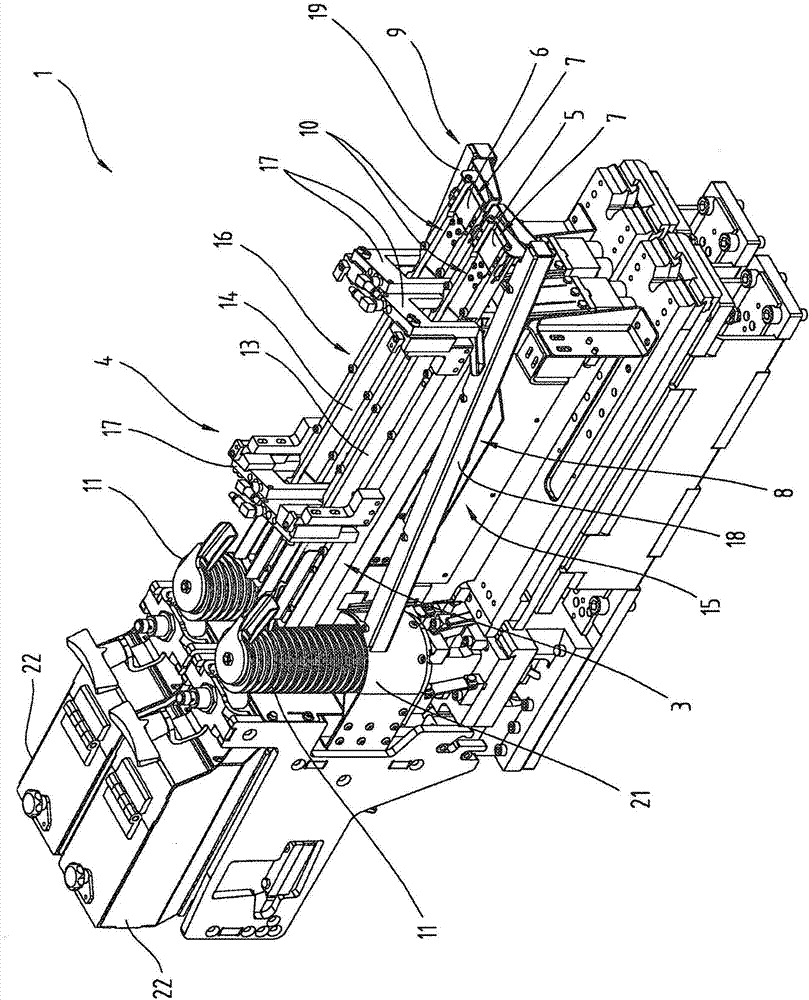
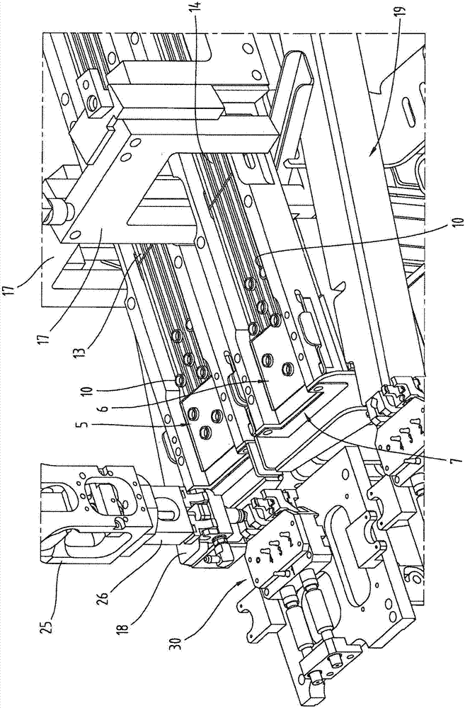
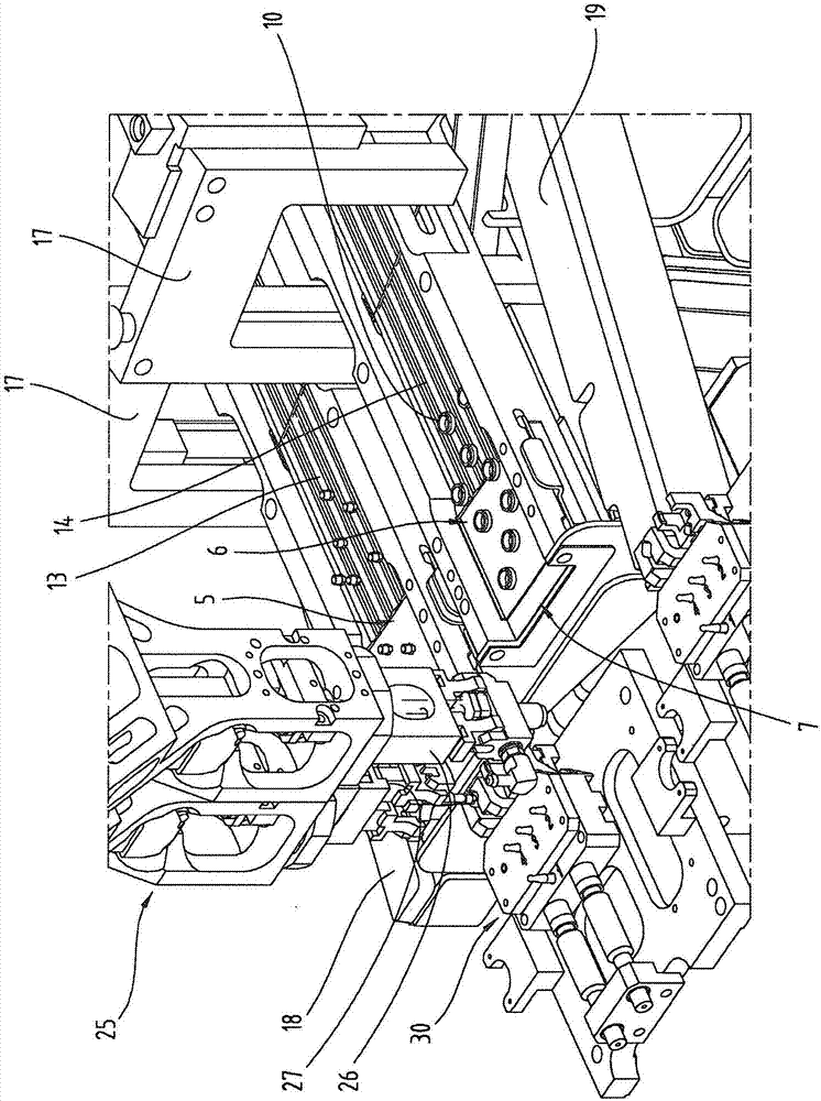
The invention relates to a component preparation device (1) for a production plant (2), comprising: at least one preparation platform (5, 6) and at least one feeding unit (3, 4) for feeding components (10) to the preparation platform (5, 6). In order to return excess or incorrectly oriented components to the process, at least one return device (8, 9) is provided, extending from the region of the preparation platform (5, 6) and leading into the feeding unit (3, 4), preferably in the starting region thereof. The invention also relates to a production plant for producing assemblies (30) from individual components (10) and to a method for preparing and removing components (10) in a production plant (2).

Description

technical field [0001] The invention relates to a component provisioning device for a manufacturing plant, which component provisioning device in particular comprises at least one provisioning platform and at least one introduction device for introducing components into the supplying platform. The invention also relates to a production plant for producing structural components from individual components and a method for supplying and removing components in a production plant. Background technique [0002] EP2393739B1 (or US2011284344A1) discloses a system for supplying structural elements comprising a vibration device. The structural elements are removed from the plate as receiving surface by means of a robot. The visualization system arranged above the plate is designed to detect the position of the structural elements on the plate of the vibration device and to manipulate the vibration device and the robot as a function of the distribution and orientation of the structura...

Claims


Application Information

Patent Timeline
Patent Type & Authority Applications(China)
IPC IPC(8): B65G27/04B65G47/14B65G47/256B65G47/51
CPCB65G47/74B65G27/04B65G47/145B65G47/256B65G47/5145
Inventor J·克里茨卿格
Owner STIWA HLDG
Learn More