
A method for realizing electronic fence system

An electronic fence and fence technology, applied in the field of communication, can solve the problems of vehicles unable to be locked, the antenna signal range is large, and cannot be accurately positioned, and achieve the effect of receiving signals without dead ends, assisting planning areas, and accurate communication ranges.

Inactive Publication Date: 2018-07-27
BEIJING HAOLUO TECH
View PDF3 Cites 0 Cited by
  • Summary
  • Abstract
  • Description
  • Claims
  • Application Information

AI Technical Summary

Problems solved by technology

The disadvantage of the above-mentioned method through virtual positioning technology is that it requires more accurate and complex algorithms, and is greatly affected by the surrounding environment, so it cannot be precisely positioned
The second type is an electronic fence based on virtual positioning technology combined with parking point signal devices. Large, the coverage often exceeds the planned area, and the shape of the electronic fence is restricted by the external environment, which is not conducive to the establishment of parking fences
When the vehicle is parked beyond the area stipulated by the system, the vehicle will not be able to be locked, and the background will always be billed

Method used


Image

  • A method for realizing electronic fence system
  • A method for realizing electronic fence system
  • A method for realizing electronic fence system

Examples


Embodiment Construction

[0034] Obviously, many modifications and changes made by those skilled in the art based on the gist of the present invention belong to the protection scope of the present invention.

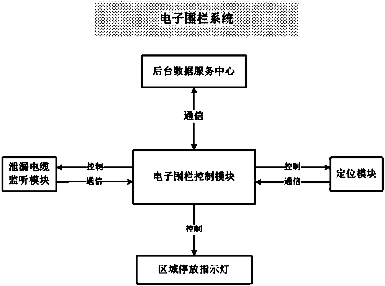
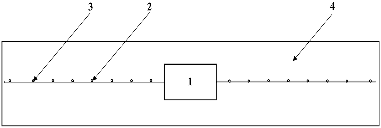
[0035] The designed electronic fence system mainly includes: electronic fence control module, leakage cable monitoring module, background data service center, and can further include positioning module and area parking indicator light, etc., such as figure 1 shown. The electronic fence control module is mainly responsible for controlling and coordinating the entire system, completing the work process, and performing real-time data interaction with the background data service center to obtain big data information such as the frequency of shared vehicles, parking status, number of vehicles, and parking locations; the leakage cable monitoring module is mainly Responsible for planning the signal receiving range, and reporting the number of shared cars in the electronic fence to the electronic fence c...


PUM


Abstract

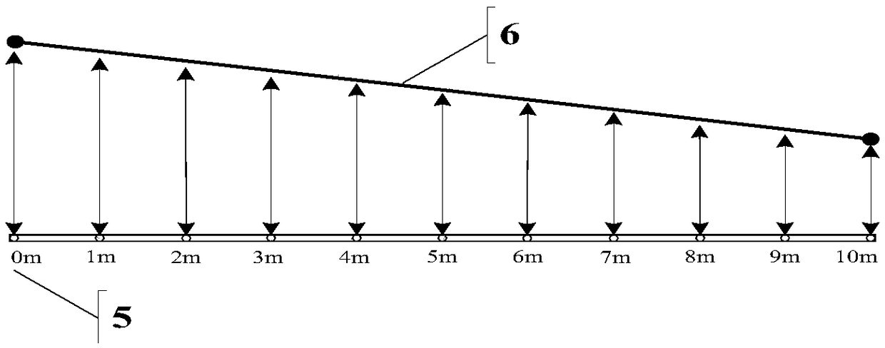
The invention relates to a method for realizing an electronic fence system. The method includes the following steps that: a leaky cable monitoring module is adopted to plan a signal receiving range and report monitored shared bicycle information in an electronic fence to an electronic fence control module; the electronic fence control module acquires the shared bicycle information in the electronic fence and exchanges information data in real time with a backstage data service center; the backstage data service center processes exchanged data to obtain big data information such as the use frequencies, parking states, number and parking positions of shared bicycles and monitors the status information of the shared bicycles; and the positioning and calculation unit of the electronic fence control module calculates distances between the signal emitting ends of the shared bicycles parked in the electronic fence and the signal receiving end of the leaky cable monitoring module and obtains the parking position information of the shared bicycles. According to the method of the invention, a leakage cable technology and a positioning and calculation algorithm are combined together, so that detection precision can be further improved; and a coverage range can be adjusted, so that the coverage range of the electronic fence can be more regular and accurate.

Description

technical field [0001] The invention relates to the communication field, in particular to a method for realizing an electronic fence system. Background technique [0002] With the rapid development of the Internet, the sharing economy has become popular nowadays, and shared transportation tools have emerged as the times require. The "geometric" replication of short-term business models has also brought many management problems. Already is the biggest problem right now. The electronic fence technology solves this situation to the greatest extent. The essence of the electronic fence is a "fence". It uses the Internet of Things chip to transmit signal coverage technology to form a virtual parking frame, and demarcate an area for shared vehicles to park. Can be parked within the specified range. [0003] The parking method of auxiliary electronic fence technology is roughly divided into two development directions: the first is to realize the electronic fence through virtual po...

Claims


Application Information

Patent Timeline
Patent Type & Authority Patents(China)
IPC IPC(8): G08G1/00G01S19/42
CPCG01S19/42G08G1/205
Inventor 常永利
Owner BEIJING HAOLUO TECH
Learn More