
Small special electrical machine stator shaping device

A shaping device and micro-motor technology, applied in electromechanical devices, manufacturing motor generators, manufacturing stator/rotor bodies, etc., can solve the problems of unable to achieve synchronous expansion of stator coils, simple stator coil shaping structure, poor shaping effect, etc. Achieve the effect of increasing the early warning function of clamping in place, high reliability, and improving the effect of shaping

Inactive Publication Date: 2017-11-21
ZHONGSHAN HUAMEITE ELECTRICAL APPLIANCE MFG
View PDF0 Cites 8 Cited by
  • Summary
  • Abstract
  • Description
  • Claims
  • Application Information

AI Technical Summary

Problems solved by technology

[0003] In the prior art, there are still many deficiencies in the stator shaping device for micro and special motors. It has a simple structure for shaping the stator coils, and cannot realize synchronous expansion of the stator coils, and the shaping effect is poor; the existing stator shaping devices for micro and special motors In the process of clamping the stator, it is easy to deform the stator due to excessive extrusion, and the operation is difficult; when the stator is accidentally dropped, the existing micro-motor stator shaping device is prone to hard collisions, which can easily cause product damage , so there is an urgent need for a new type of micro-motor stator shaping device to solve the above-mentioned problems

Method used


Image

  • Small special electrical machine stator shaping device
  • Small special electrical machine stator shaping device
  • Small special electrical machine stator shaping device

Examples


Embodiment Construction

[0021] In order to make the technical means, creative features, goals and effects achieved by the present invention easy to understand, the present invention will be further described below in conjunction with specific embodiments.

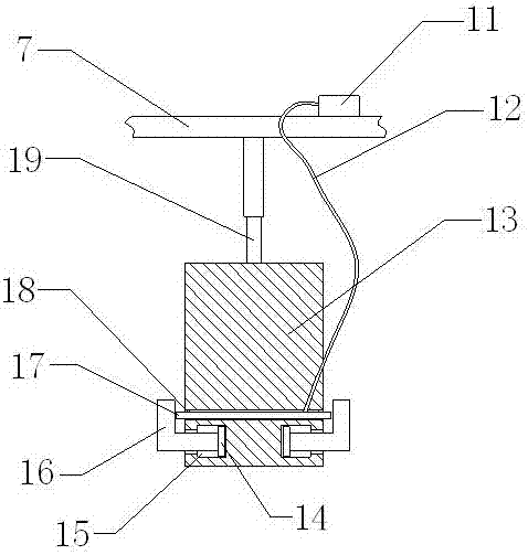
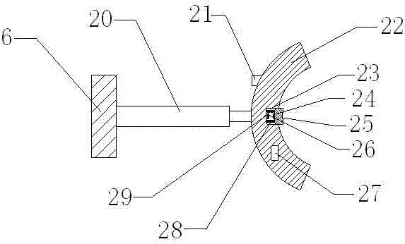
[0022] see Figure 1-Figure 4 , the present invention provides a technical solution: a micro-motor stator shaping device, including a device main body, an air pressure expansion shaping mechanism 1, an anti-pinching mechanism 2 and an anti-hard collision mechanism 3, and the device main body includes a vertical plate 4 and a base 5 , vertical plate two 6 and upper flat plate 7, the lower end of vertical plate one 4 is installed on the right side of the upper end surface of base 5, the lower end of vertical plate two 6 is installed on the left side of the upper end surface of base 5, and the left end of upper flat plate 7 is installed on the right end surface of vertical plate two 6 At the upper corner, the right end of the upper plate 7 is assembl...


PUM


Abstract

The invention provides a stator shaping device for a micro-special motor, which includes an air pump, a limiting plate, a shaping plate, a rubber balloon, an annular groove, an alarm bell, a contact piece 1, a front plate, a contact piece 2 and a battery. Set on the lower side of the circular side of the cylinder, the rubber balloon is assembled in the annular groove, the limiting plate is assembled in the hollow cavity, the shaping plate is arranged outside the cylinder, and the air pump is assembled on the upper end surface of the upper plate , this design achieves the purpose of synchronous expansion and shaping in the present invention, the alarm bell is assembled on the arc-shaped outer surface of the arc-shaped splint, the first contact piece is installed at the middle position of the left end surface of the front plate, and the second contact piece is assembled on the insulating On the right end of the plate, the storage battery is arranged in the arc-shaped splint. This design increases the early warning function of the present invention for clamping the stator in place. The present invention is easy to use, simple to operate, good in stability and high in reliability.

Description

technical field [0001] The invention relates to a stator shaping device for a micro-special motor, which belongs to the technical field of motor production. Background technique [0002] Micro motor, the full name of micro special motor, referred to as micro motor, refers to a micro motor with a diameter of less than 160mm or a rated power of less than 750W or with special performance and special purposes. Micro motors are often used in control systems to realize functions such as detection, calculation, amplification, execution or conversion of electromechanical signals or energy, or for transmission of mechanical loads, and can also be used as AC and DC power supplies for equipment. [0003] In the prior art, there are still many deficiencies in the stator shaping device for micro and special motors. It has a simple structure for shaping the stator coils, and cannot realize synchronous expansion of the stator coils, and the shaping effect is poor; the existing stator shapi...

Claims


Application Information

Patent Timeline
IPC IPC(8): H02K15/02H02K15/00
CPCH02K15/02H02K15/0025
Inventor 汪日松李延杰李健标
Owner ZHONGSHAN HUAMEITE ELECTRICAL APPLIANCE MFG
Learn More