Improved type auxiliary minimally invasive spinal surgical pathway positioning device

A technology of minimally invasive surgery and positioning device, which is applied in the field of surgical instruments and can solve the problems of deviation from the set path, difficult operation, and low accuracy of spinal drilling.

Pending Publication Date: 2017-11-17
苏州铸正机器人有限公司
View PDF0 Cites 1 Cited by
  • Summary
  • Abstract
  • Description
  • Claims
  • Application Information

AI Technical Summary

Problems solved by technology

Due to the complexity of the anatomical structure of the spine and the limitations of the doctor's means of observing the spine, the operation is very difficult; the drilling accuracy of the spine is not high, and the drilling operation deviates from the set path; in addition, the repeated use of X-ray fluoroscopy makes the doctor, Patients and related personnel are exposed to radiation for a long time

Method used


Image

  • Improved type auxiliary minimally invasive spinal surgical pathway positioning device
  • Improved type auxiliary minimally invasive spinal surgical pathway positioning device
  • Improved type auxiliary minimally invasive spinal surgical pathway positioning device

Examples


Embodiment Construction

[0033] Specific embodiments of the present invention will be described below in conjunction with the accompanying drawings.

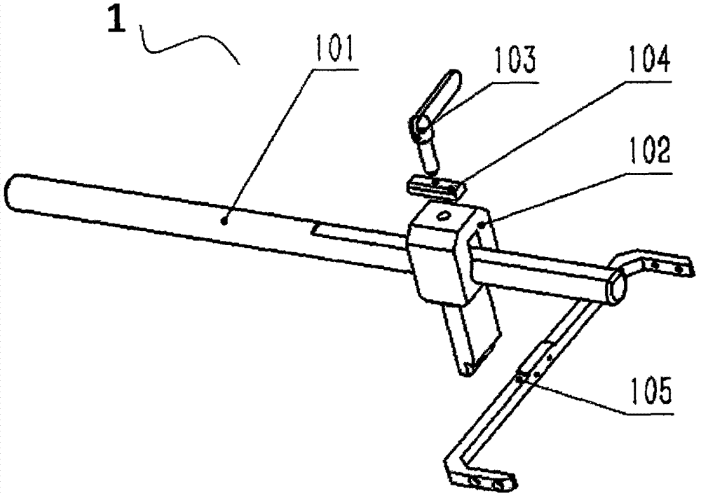
[0034] refer to Figure 1 to Figure 8 , an embodiment of the improved path positioning device for auxiliary spinal minimally invasive surgery of the present invention, including a fixed assembly 1, a lateral translation assembly 2, a longitudinal translation assembly 3, a longitudinal rotation assembly 4, a lateral rotation assembly 5, an angle indication assembly 6 and a lift slide assembly7. The longitudinal translation assembly 3 drives the double annulus to move longitudinally by keeping the double annulus stationary relative to the rotation assembly 4, that is, the longitudinal translation assembly 3 drives the double annulus to move longitudinally, and ensures that the double annulus moves vertically during the longitudinal movement. It is stationary relative to the rotating assembly 5 . The lateral translation assembly 2 drives the double rings...


PUM


Abstract

The invention relates to an improved type auxiliary minimally invasive spinal surgical pathway positioning device. The improved type auxiliary minimally invasive spinal surgical pathway positioning device mainly comprises a fixed assembly, a transverse translational assembly, a longitudinal translational assembly, a lifting slide assembly, a longitudinal rotating assembly, a transverse rotating assembly and an angle indicating assembly. The fixed assembly is fixedly connected with a surgical bed or a trolley; a transverse positioning assembly can drive a rotating assembly and a longitudinal positioning assembly to conduct longitudinal translation; the longitudinal translational assembly can drive the lifting slide assembly and the rotating assembly to conduct transverse translation; the lifting slide assembly can drive the rotating assembly to adjust in the direction of a sliding rail; the longitudinal rotating assembly can drive the transverse rotating assembly to rotate along a rotary shaft; and the angle indicating assembly can indicate the rotating angle of the rotating assembly. The rotary shaft of the transverse rotating assembly is parallel to the translational direction of the transverse translational assembly which moves transversely, and a rotary shaft of the longitudinal rotating assembly is parallel to the translational direction of the longitudinal translational assembly. A first positioning ring and a second positioning ring which are used for supplying a guide needle to penetrate sequentially to position the transverse rotating assembly are arranged on the transverse rotating assembly, and the first positioning ring and the second positioning ring are spaced from each other and arranged concentrically. The centers of the two positioning rings are located on the rotary shaft of the longitudinal rotating assembly. The adjusting device can assist doctors to rapidly and accurately position the minimally invasive spinal surgical implantation pathway under the situation that the radiation frequency is low.

Description

technical field [0001] The invention relates to a surgical instrument, in particular to an improved path positioning device for auxiliary spinal minimally invasive surgery. Background technique [0002] Minimally invasive spinal surgery requires less traction and stripping of soft tissues, which can reduce postoperative pain and shorten recovery time; and minimally invasive spinal surgery performs limited resection of bony structures, thereby reducing the possibility of postoperative spinal instability. Therefore, minimally invasive spinal surgery techniques have developed rapidly in the past decade. Minimally invasive spinal surgery mainly includes microscopic discectomy under minimally invasive access, minimally invasive lumbar hemilaminectomy, transforaminal lumbar interbody fusion, lateral lumbar interbody fusion, and minimally invasive posterior approach fixed technology. Compared with traditional open surgery, due to the need for minimally invasive tunnel positioning...

Claims


Application Information

Patent Timeline
IPC IPC(8): A61B90/11
CPCA61B90/11A61B2090/101
Inventor 胡磊于晓亮郭娜王利峰孙贝
Owner 苏州铸正机器人有限公司
Why Eureka
Try Eureka