Multichannel parallel optical receiving module

A light-receiving component and multi-channel technology, applied in optical components, light guides, optics, etc., can solve problems such as modules that cannot meet requirements, achieve the effects of reducing difficulty requirements, easy assembly, and reducing difficulty

Pending Publication Date: 2017-11-10
HISENSE & JONHON OPTICAL ELECTRICAL TECH CO LTD
View PDF6 Cites 5 Cited by
  • Summary
  • Abstract
  • Description
  • Claims
  • Application Information

AI Technical Summary

Problems solved by technology

At present, with the increase of the communication distance between data centers, the requirements for the communication distance between modules are getting higher and higher. The original multi-channel multi-mode parallel optical module can no longer meet the requirements of communication distance, and the multi-channel single-mode parallel optical module should be used. However, the multi-channel single-mode parallel optical module is limited by the volume and number of channels of coaxial packaged TOSA and ROSA optical components, and it is increasingly unable to meet the needs of the development of modules in the direction of high integration and small volume.

Method used


Image

  • Multichannel parallel optical receiving module
  • Multichannel parallel optical receiving module
  • Multichannel parallel optical receiving module

Examples


Embodiment Construction

[0011] The specific embodiments of the present invention will be described in detail below, and it should be understood that the specific embodiments described here are only used to illustrate and explain the present invention, and are not intended to limit the present invention.

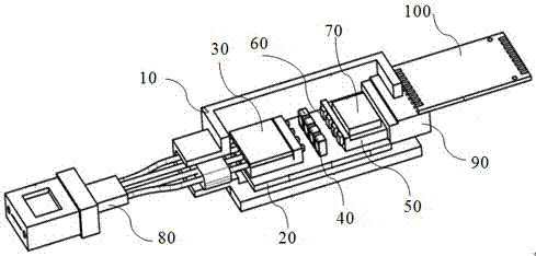
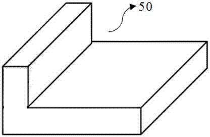
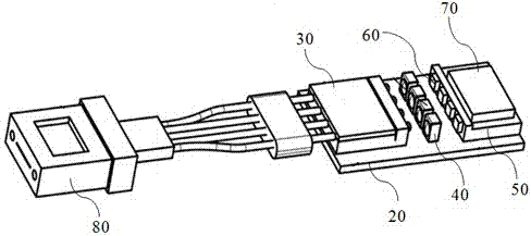
[0012] Such as Figure 1-Figure 3 As shown, the multi-channel parallel light-receiving assembly of this embodiment includes a housing 10, a substrate 20, an MT connector 80, a ceramic terminal 90, and a flexible circuit board 100. The substrate 20 is arranged inside the housing 10; Collimation array 30, focusing lens 40 and L-shaped spacer 50, photodetector PD60 is installed on the side of L-shaped spacer 50, receiving drive chip 70 is installed on the top of L-shaped spacer 50; Photodetector PD60 and receiving drive The chip 70 is connected by a gold wire; the optical fiber collimation array 30, the focusing lens 40 and the photodetector PD60 can realize optical coupling.

[0013] In this embodime...


PUM


Abstract

The invention discloses a multichannel parallel optical receiving module, and the optical receiving module comprises a housing, a substrate, an MT connector, a ceramic terminal, and a flexible circuit board. The substrate is disposed in the housing. The substrate is provided with an optical fiber collimation array, a focusing lens and an L-shaped gasket, wherein the optical fiber collimation array, the focusing lens and the L-shaped gasket are set sequentially. A side surface of the L-shaped gasket is provided with a photoelectric detector PD, and a receiving drive chip is disposed above the L-shaped gasket. The photoelectric detector PD and the receiving drive chip are connected through bonding. The optical fiber collimation array, the focusing lens and the photoelectric detector PD achieve the optical path coupling. According to the invention, the module employs a fewer optical devices, can greatly reduce the coupling difficulty of the optical path, reduces the technological difficulty and requirements during the production of the module, is easier to assemble, improves the production efficiency of the module, facilitates the batch product, and can achieve the airtightness.

Description

technical field [0001] The invention relates to the technical field of optical fiber communication, in particular to a multi-channel parallel light receiving component. Background technique [0002] In the field of data communication, in order to improve the transmission bandwidth of information and enhance the throughput of data, on the one hand, to increase the communication capacity of a single channel, wavelength division multiplexing technology is often used, and wavelength division multiplexing optical modules are used; Quantity, parallel transmission technology is often used, and multi-channel parallel optical modules are used. At present, with the increase of the communication distance between data centers, the requirements for the communication distance between modules are getting higher and higher. The original multi-channel multi-mode parallel optical module can no longer meet the requirements of communication distance. The multi-channel single-mode parallel optic...

Claims


Application Information

Patent Timeline
IPC IPC(8): G02B6/42
CPCG02B6/4206G02B6/4237G02B6/4281G02B6/4286G02B6/4287
Inventor 张朝惠张帅谭先友
Owner HISENSE & JONHON OPTICAL ELECTRICAL TECH CO LTD
Why Eureka
Try Eureka