
Cable bender

A bender and cable technology, applied in the field of wire bending devices, can solve the problem of small contact area between the cable head and the busbar

Inactive Publication Date: 2017-11-10
STATE GRID SHANDONG ELECTRIC POWER +1
View PDF7 Cites 7 Cited by
  • Summary
  • Abstract
  • Description
  • Claims
  • Application Information

AI Technical Summary

Problems solved by technology

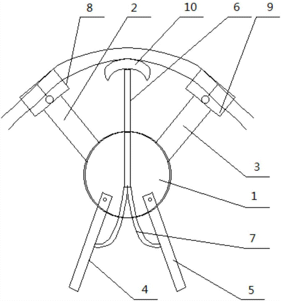
[0007] The purpose of the present invention is to overcome the above-mentioned defects and propose a cable bender. By setting the clamp body and the ejection mechanism, the cable head can be bent to a standard arc, solving the problem of small contact area between the cable head and the busbar caused by manual bending of the cable head, and improving Improve the on-site work efficiency of cable bending, avoid direct contact between the staff and the cable, and improve the safety of operation

Method used


Image

  • Cable bender
  • Cable bender

Examples


Embodiment Construction

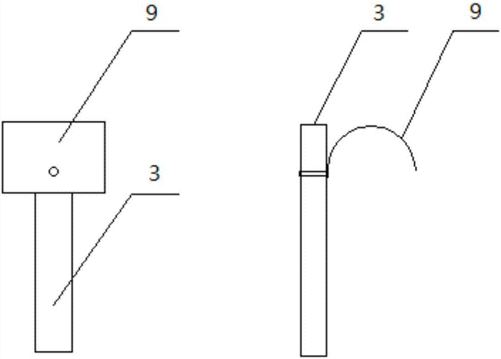
[0027] The present invention will be further described below in conjunction with accompanying drawing.

[0028] Such as figure 1 , 2 As shown, the cable bender of the present invention includes: a pliers body, including a connecting part 1, a first support rod 2 fixed on the upper part of the connecting part 1, and a second supporting rod 3 symmetrically arranged on the upper part of the connecting part, hinged and symmetrically arranged on the lower part of the connecting part The first holding rod 4 and the second holding rod 5; the ejector mechanism includes the ejector rod 6 and the elastic rod 7 connected to the end of the ejector rod 6 and bifurcated to both sides; the ends of the elastic rod 7 are respectively connected to the first The first holding bar 4 and the second holding bar 5 are fixedly connected, and the top ends of the first support bar 2 and the second support bar 3 are hinged to the first card slot part 8 and the second card slot part 9 for engaging the c...


PUM


Abstract

The invention relates to a cable bending device, in particular to a cable bender suitable for transformer and high and low voltage cabinet cable distribution. The cable bender aims to solve the problem that the contact area of a cable head and a busbar is small due to hand bending of the cable head by arranging a plier body and an ejection mechanism to enable the bending radian of the cable head to be standard, site working efficiency of cable bending is improved, direct contact of staff and a cable is avoided, and operation safety is improved. The cable bender comprises the plier body and the ejection mechanism, wherein the plier body comprises a connecting part, a first supporting rod, a second supporting rod, a first holding rod and a second holding rod, the first supporting rod and the second supporting rod are fixed at the upper portion of the connecting part and arranged symmetrically, and the first holding rod and the second holding rod are hinged to the upper portion of the connecting part and arranged symmetrically; the ejection mechanism comprises an ejection rod and an elastic rod, the elastic rod is connected with the tail end of the ejection rod and is forked and bent to two sides, the tail end of the ejection rod is fixedly connected with the first holding rod and the second holding rod, the top end of the first supporting rod and the top end of the second supporting rod are hinged to a first clamping groove part and a second clamping groove part, and the first clamping groove part and the second clamping groove part are used for clamping the cable.

Description

technical field [0001] The invention relates to a wire bending device, in particular to a cable bender suitable for distribution cables of transformers and high and low voltage cabinets. Background technique [0002] In normal work, the crimping cables of transformers and high and low voltage cabinets are bent by hand. At present, there is no small tool that has been formed to replace the bending work of cables done by hand. The cable bending done by hand mainly has the following disadvantages: [0003] 1. The craftsmanship of different construction teams is uneven, and there is no unified and standardized standard, which affects the acceptance of later results. [0004] 2. The unevenness of the process affects the aesthetics of the installation and brings challenges to the standard management of the power distribution room. [0005] 3. The bending degree of the cable is too small, so that the contact area between the cable head and the equipment busbar is too small, the ...

Claims


Application Information

Patent Timeline
IPC IPC(8): B21F1/00
CPCB21F1/002
Inventor 石琳刘立阳杨伟王友琳徐晓涛姜凯潘富杰孙宇斌李松谢志平孙晔谭林斌赵传让张涛董博超王利王超王肖亚毕凯郑朝王所钺李国成苏海勇张华珍张沈阳贾希剑徐伟尹文杰孙凯刘新鑫张强徐天锡王春勇王小青孙奉杰王岩曲克强李同全刘持军商爱民王光通孙奉林宋鹏黄新良王鑫泽刘恺韩涛王勇孙丰进隋中东乔宏业孔淑李雪媛
Owner STATE GRID SHANDONG ELECTRIC POWER
Learn More