Convenient and rapid cleaning equipment

A cleaning equipment and a convenient technology, applied in the field of cleaning, can solve the problems of high labor intensity, poor effect, low efficiency, etc., and achieve the effects of simple structure, improved cleaning efficiency, and convenient installation and disassembly

Inactive Publication Date: 2017-11-03
慈溪市隆诚贸易有限公司
View PDF0 Cites 1 Cited by
  • Summary
  • Abstract
  • Description
  • Claims
  • Application Information

AI Technical Summary

Problems solved by technology

[0002] The rods with helical patterns on the surface need to be washed after the production is completed to clean up the dust in the gaps between the helical patterns. When cleaning, workers generally use water guns to clean them. This cleaning method is labor-intensive and inefficient. However, some convenient cleaning equipment on the market are extensive operations, which cannot effectively clean every crevice, and the effect is poor, so they are not suitable for products with high precision requirements.

Method used


Image

  • Convenient and rapid cleaning equipment
  • Convenient and rapid cleaning equipment
  • Convenient and rapid cleaning equipment

Examples


Embodiment Construction

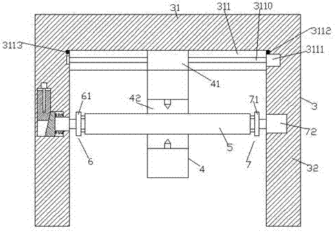
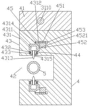
[0021] Such as figure 1 , figure 2 with image 3 As shown, a convenient cleaning device of the present invention includes a base body 3 composed of a top beam 31 and vertical rods 32 fixed on the left and right sides of the top beam 31. Connecting groove 311, the sliding connecting groove 311 is provided with the first screw rod 3110 extending left and right, the inner screw of the first screw rod 3110 is connected with the sliding joint block 41, and the bottom of the sliding joint block 41 is provided with a cleaning Device 4, the front end of the cleaning device 4 is provided with a working tank 42, and the cleaning device 4 on the upper and lower sides of the working tank 42 is oppositely provided with a first sliding joint cavity 43, and the first sliding joint cavity 43 is separated from the One side of the working groove 42 is provided with a second sliding joint cavity 45 elongated to the right and arranged through each other. The second sliding joint cavity 45 is p...


PUM


Abstract

The invention discloses a convenient cleaning device, which comprises a base composed of a top beam and vertical bars fixed on the left and right bottoms of the top beam. A sliding joint groove is arranged in the end surface of the bottom of the top beam, and the sliding joint groove is provided with left and right elongated The first screw rod is set, and the first screw rod is screw-fitted with a sliding joint block. The bottom of the sliding joint block is provided with a cleaning device. The front end of the cleaning device is provided with a working tank. The first sliding connection cavity, the first sliding connection cavity is provided with a second sliding connection cavity extending to the right side and penetrating with each other on the side away from the working tank. The second sliding connection cavity is provided with a second screw rod extending left and right. The upper part of the two screw rods is spirally connected with a lower pressure block, and the inner wall on the right side of the first sliding joint cavity is provided with a protrusion on the side of the working groove, and the first sliding joint cavity is connected with a vertical sliding joint block; the structure of the present invention is simple , easy installation and disassembly, high cleaning efficiency, and can meet the cleaning work of rods of different diameters.

Description

technical field [0001] The invention relates to the technical field of cleaning, in particular to a convenient cleaning device. Background technique [0002] The rods with helical patterns on the surface need to be washed after the production is completed to clean up the dust in the gaps between the helical patterns. When cleaning, workers generally use water guns to clean them. This cleaning method is labor-intensive and inefficient. However, some convenient cleaning equipment on the market are extensive operations, which cannot effectively clean every crevice, and the effect is poor, so they are not suitable for products with high precision requirements. Contents of the invention [0003] The technical problem to be solved by the present invention is to provide a convenient cleaning device, which can solve the above-mentioned problems in the prior art. [0004] The present invention is achieved through the following technical solutions: a convenient cleaning device of t...

Claims


Application Information

Patent Timeline
Patent Type & Authority Applications(China)
IPC IPC(8): B08B3/02B08B13/00
CPCB08B3/02B08B13/00
Inventor 程佩芳
Owner 慈溪市隆诚贸易有限公司
Why Eureka
Try Eureka