
Universal lifting frame for steel structure modular houses, and spot hoisting in-position method of universal lifting frame

A steel structure, modular technology, applied in the directions of transportation and packaging, load hanging components, etc., can solve problems such as increased cost, increased material investment, difficult module box deformation, etc., to reduce the cost of measures, improve efficiency, and high efficiency. The effect of adjustment

Inactive Publication Date: 2017-10-27
MCC TIANGONG GROUP +1
View PDF8 Cites 9 Cited by
  • Summary
  • Abstract
  • Description
  • Claims
  • Application Information

AI Technical Summary

Problems solved by technology

In the prior art, hoisting has a great influence on the quality of the module box, and it is difficult to control the deformation of the corresponding module box, thus affecting the safety of the main structure and the integrity of the decoration
It is necessary to consider the corresponding strengthening of the main body of the structure, resulting in increased material investment and higher costs; the simultaneous positioning of the four corner fittings requires a lot of labor, and the adjustment operation is inconvenient and the efficiency is low

Method used


Image

  • Universal lifting frame for steel structure modular houses, and spot hoisting in-position method of universal lifting frame
  • Universal lifting frame for steel structure modular houses, and spot hoisting in-position method of universal lifting frame
  • Universal lifting frame for steel structure modular houses, and spot hoisting in-position method of universal lifting frame

Examples


Embodiment Construction

[0031] It should be noted that, in the case of no conflict, the embodiments of the present invention and the features in the embodiments can be combined with each other.

[0032] In describing the present invention, it should be understood that the terms "center", "longitudinal", "transverse", "upper", "lower", "front", "rear", "left", "right", The orientations or positional relationships indicated by "vertical", "horizontal", "top", "bottom", "inner", "outer", etc. are based on the orientation or positional relationships shown in the drawings, and are only for the convenience of describing the present invention Creation and simplification of description, rather than indicating or implying that the device or element referred to must have a specific orientation, be constructed and operate in a specific orientation, and therefore should not be construed as limiting the invention. In addition, the terms "first", "second", etc. are used for descriptive purposes only, and should no...


PUM


Abstract

The invention provides a universal lifting frame for steel structure modular houses. The universal lifting frame comprises a lifting frame body and a steel wire rope which is arranged on the lifting frame body and is used for lifting; the steel wire rope is connected with a chain jack used for adjusting the unilateral inclination degree of the lifting frame body; the lifting frame body comprises a gate type frame and a reinforced support piece arranged in the middle of the gate type frame; one end of the gate type frame is directly connected with the steel wire rope, and the other end of the gate type frame is connected with the chain jack arranged on the steel wire rope; a lower lifting lug used for connecting a lifting band is arranged at the lower side of the lifting frame body, and the upper end of the lifting frame body is provided with an upper lifting lug connected with the chain jack or the steel wire rope. According to the universal lifting frame, the chain jack is additionally arranged at one side of the steel wire rope used for lifting, so that the efficient adjustment of module in position can be realized; the universal lifting frame is simple to operate; after the universal lifting frame is adopted, the measure cost is lowered while high quality assurance is obtained, and the efficiency is increased; therefore, the universal lifting frame for the steel structure modular houses is widely popularized and applied to a module manufacturing process.

Description

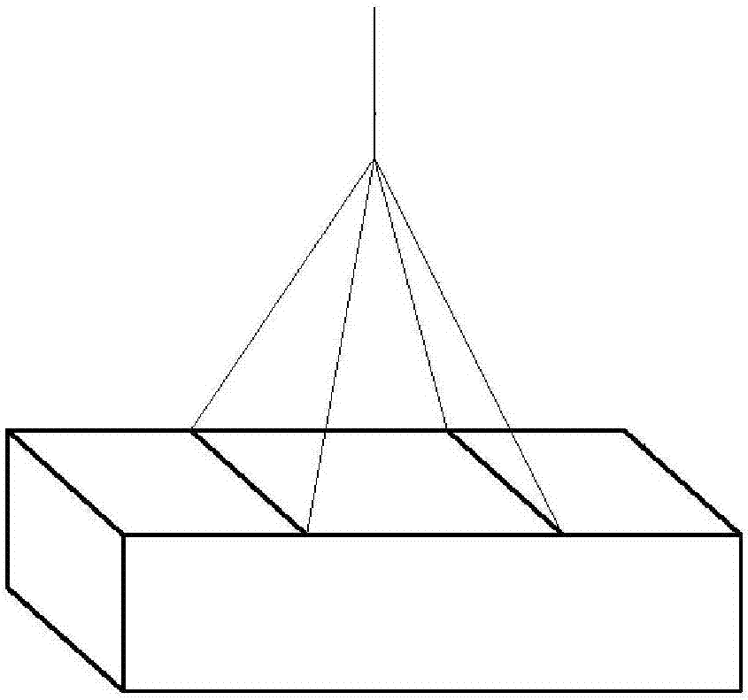
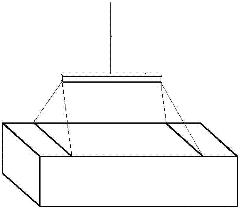
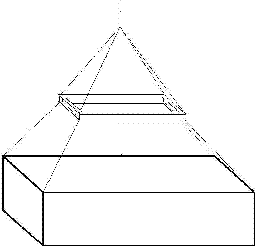
technical field [0001] The invention belongs to the technical field of steel structure modular buildings, and in particular relates to a general hanger for a steel structure modular building and a method for hoisting in place on site. Background technique [0002] Steel structure modular building is a highly integrated prefabricated building, which is usually fully prefabricated in the factory and transported to the site for the overall hoisting of individual modules in place, and then the overall building is formed after the modules are stacked. At present, the on-site hoisting method of modular houses generally adopts a one-point hoisting method (such as figure 1 Directly hoisting on the modular steel beam with steel wire rope at an angle), beam hoisting method (such as figure 2 hoisting the steel wire rope on the modular steel beam at an angle through the crossbeam), the lifting hoisting method of the secondary frame (such as image 3 The steel wire rope is hoisted on ...

Claims


Application Information

Patent Timeline
IPC IPC(8): B66C1/12B66C13/08
CPCB66C1/12B66C13/08
Inventor 李显峰高春生王延臣高振旭胡帅王俊伟张艳花
Owner MCC TIANGONG GROUP
Learn More