


Quick Research
Generate reliable direction feasibility study reports for your R&D in just a few steps.

Technical Q&A
Discover and master advanced knowledge NOW. Basics, ideas, possibilities, all at once.

Find Solutions
As an expert in R&D theories, this can generate solutions to your technical problems instantly.

Evaluate Feasibility
Analyze your overall solution with one click, know your potential R&D risks in advance.

Monitor Landscape
Get weekly tech updates, stay abreast of the latest tech innovations and key insights.
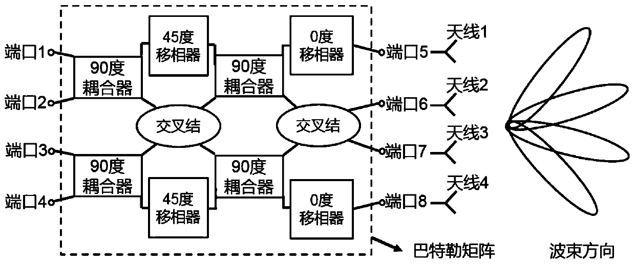
A Butler Matrix Network Structure Based on Dielectric Integrated Suspension Lines
A Butler matrix and medium integration technology, applied in the field of Butler matrix network structure, can solve the problems of difficult circuit layout and large loss, and achieve the effects of low processing cost, low loss and reduction of radiation loss.
- Summary
- Abstract
- Description
- Claims
- Application Information
AI Technical Summary
Problems solved by technology
Method used
Image

Examples
Embodiment 1
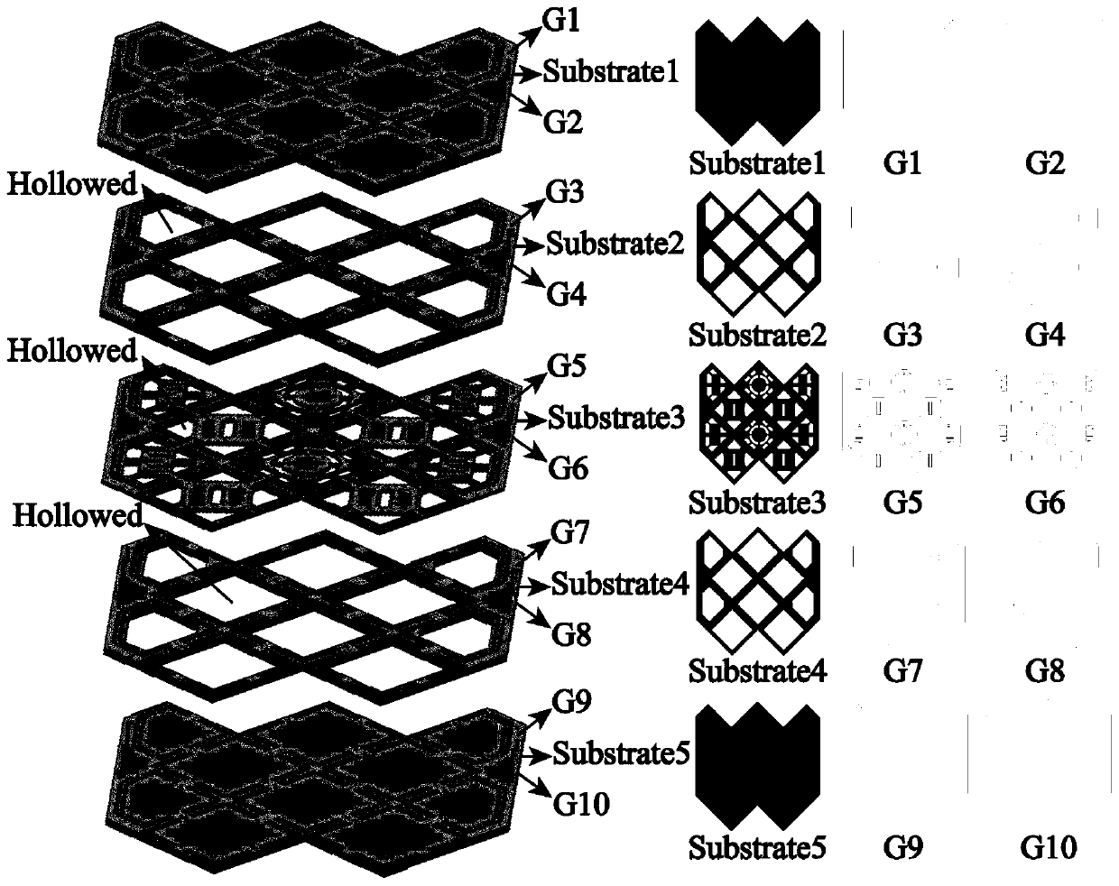
[0051] Embodiment 1: The five-layer dielectric substrate is selected as:
[0052] Substrate1: Fr4 material, thickness 0.6mm, dielectric constant 4.4;
[0053] Substrate2: Fr4 material, thickness 0.6mm, dielectric constant 4.4;
[0054] Substrate3: Rogers5880 material, plate thickness 0.25mm, dielectric constant 2.2;
[0055] Substrate4: Fr4 material, thickness 0.6mm, dielectric constant 4.4;
[0056] Substrate5: Fr4 material, thickness 0.6mm, dielectric constant 4.4;
[0057] The design frequency band of the Butler matrix is: the center frequency is 25.45GHz, and the bandwidth is 24.5GHz-26.5GHz.
[0058] G1 to G10 are ten metal layers. Can be copper clad or gold plated.
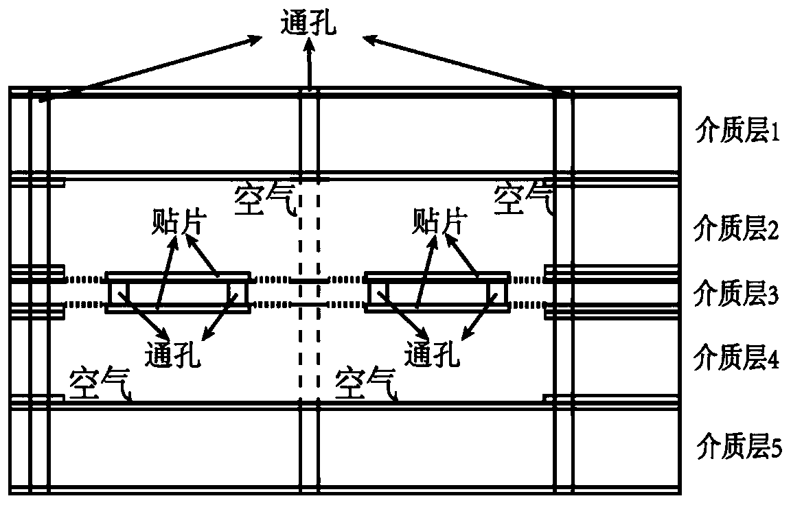
[0059] Both the coupler and the cross junction adopt a patch-shaped structure, and the phase shifter adopts a bent-line structure. In order to reduce the loss of the circuit, we proceed from three aspects: radiation loss, conductor loss, and dielectric loss. As shown in the cross-sectional view, all t...
Embodiment 2
[0061] The five-layer dielectric substrate is selected as:
[0062] Substrate1: Fr4 material, thickness 0.6mm, dielectric constant 4.4;
[0063] Substrate2: Fr4 material, thickness 0.6mm, dielectric constant 4.4;
[0064] Substrate3: Rogers5880 material, plate thickness 0.25mm, dielectric constant 2.2;
[0065] Substrate4: Fr4 material, thickness 0.6mm, dielectric constant 4.4;
[0066] Substrate5: Fr4 material, thickness 0.6mm, dielectric constant 4.4;
[0067] The design frequency band of the Butler matrix is: the center frequency is 25.45GHz, and the bandwidth is 24.5GHz-26.5GHz.
[0068] Both the coupler and the cross junction adopt a patch-shaped structure, and the phase shifter adopts a bent-line structure. Antennas are also implemented on the SISL platform. In order to reduce the loss of the circuit, we proceed from three aspects: radiation loss, conductor loss, and dielectric loss. Finally adding the transition section has been tested as Figure 9 shown. For th...
PUM
 Abstract
Description
Claims
Application Information
 - R&D Engineer
- R&D Manager
- IP Professional
- Industry Leading Data Capabilities
- Powerful AI technology
- Patent DNA Extraction
Browse by: Latest US Patents, China's latest patents, Technical Efficacy Thesaurus, Application Domain, Technology Topic, Popular Technical Reports.
© 2024 PatSnap. All rights reserved.Legal|Privacy policy|Modern Slavery Act Transparency Statement|Sitemap|About US| Contact US: help@patsnap.com