
Printing device

A technology of printing equipment and printers, which is applied in printing, transfer materials, power transmission devices, etc., and can solve the problems of large moving range of printing frame and troublesome operation

Active Publication Date: 2017-10-24
AEROSPACE INFORMATION
View PDF14 Cites 0 Cited by
  • Summary
  • Abstract
  • Description
  • Claims
  • Application Information

AI Technical Summary

Problems solved by technology

However, in such a structure, the movement range of the printing frame is relatively large, and the operation is relatively cumbersome

Method used


Image

  • Printing device
  • Printing device
  • Printing device

Examples


Embodiment Construction

[0031] Specific embodiments of the present invention will be described in detail below in conjunction with the accompanying drawings. It should be understood that the specific embodiments described here are only used to illustrate and explain the present invention, and are not intended to limit the present invention.

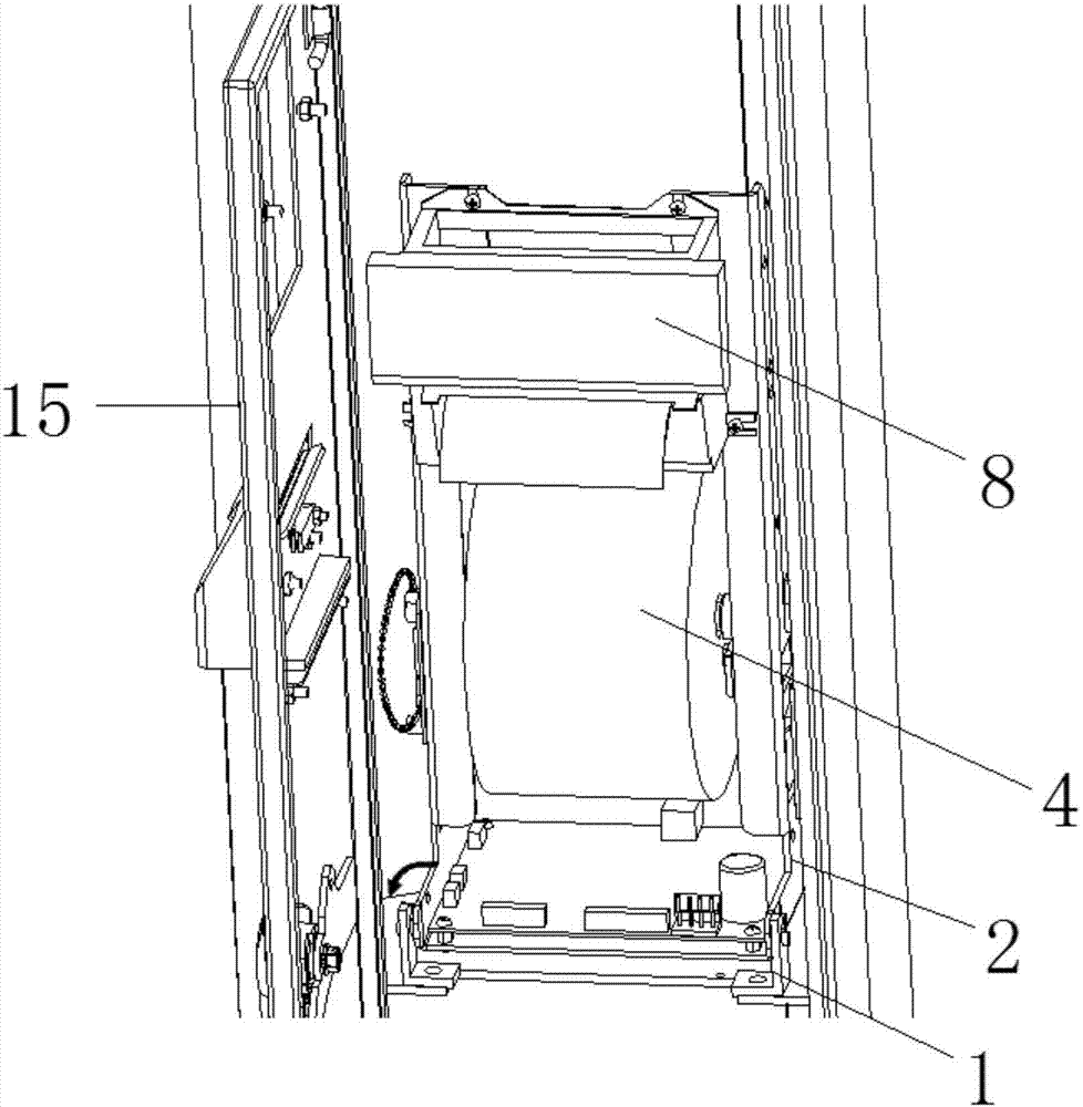
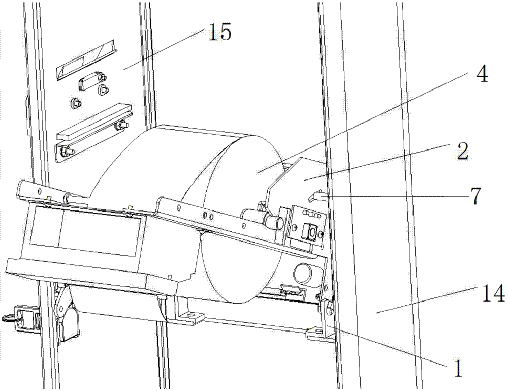
[0032] In the present invention, unless stated otherwise, the used orientation words such as "front, back, up, down, left, right" usually refer to figure 1 The position of the printing apparatus is shown with the box door 15 as the front end and, oppositely, the inside of the box-shaped housing 14 as the rear.

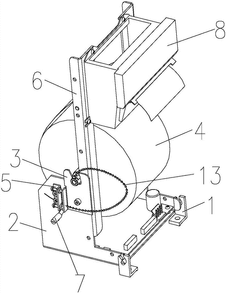
[0033] The present invention provides a printing device, comprising a box-shaped casing 14 and a printer installed in the box-shaped casing 14, the printer includes a printer installation frame 2 and a paper shaft 4, and the paper shaft 4 is installed on the printer installation frame 2, the printer installation frame 2 is pivotally installed in the box...


PUM


Abstract

The invention discloses a printing device, which comprises a box-shaped shell (14) and a printer arranged in the box-shaped shell (14), wherein the printer comprises a printer mounting frame (2) and a paper shaft (4); the paper shaft (4) is arranged on the printer mounting frame (2); the printer mounting frame (2) can be pivoted to an inclined disassembly position from a vertical mounting position at which the printer works normally; and at the inclined disassembly position, the printer stops operating, and the paper shaft (4) can be taken out from the printer mounting frame (2). Through mounting the main body part of the printer on the box-shaped shell in a pivoted mode, the main body part of the printer can be pivoted to the inclined disassembly position, a user can disassemble the paper shaft and replace the paper shaft more easily, and in comparison with a method of dragging the whole printer out, the operation steps can be simplified, a large amount of manpower can be saved, the efficiency is provided, and the danger of part damages brought by large-range moving can be avoided.

Description

technical field [0001] The present invention relates to the field of printers, in particular to a printing device. Background technique [0002] The printer used in the entry-exit channel needs to frequently replace the paper coil of the printer when the flow of people is relatively dense. In order to improve work efficiency, the replacement operation of the printer paper coil should be as simple as possible. [0003] Currently used printers include a box-shaped casing and a printer frame inside the box-shaped casing, a print head, a paper shaft, etc., wherein the printer frame carries the print head and the paper shaft, and the door of the box-shaped casing can be opened when the paper shaft needs to be replaced , pull out the printer frame as a whole and remove the paper shaft, or set a sliding track for the printer frame in the box-shaped shell to reduce the resistance of the printer frame to slide out. However, in such a structure, the moving range of the printing frame...

Claims


Application Information

Patent Timeline
IPC IPC(8): B41J25/00
CPCB41J25/00
Inventor 邓怒涛姜浩
Owner AEROSPACE INFORMATION
Learn More