Bowl lifter for kitchens

A technology of dish clamping and claws, which is applied in kitchen utensils, applications, household appliances, etc., can solve the problems of easy decoupling of the claws of the bowl taking device, inconvenient operation, and falling of the dishes, and achieves convenient operation and excellent structure. Simple, easy-to-make effects

Pending Publication Date: 2017-10-24
叶泉清
View PDF2 Cites 3 Cited by
  • Summary
  • Abstract
  • Description
  • Claims
  • Application Information

AI Technical Summary

Problems solved by technology

The structure of the existing tripod-shaped bowl remover is too simple and unreasonable. When the handle is lifted up to lift the bowl in use, the claws are forced to open outwards, and the other hand must be used to press down when operating. The claws are inconvenient to operate, and the claws of the bowl remover are easy to unhook and cause the bowl to fall

Method used


Image

  • Bowl lifter for kitchens
  • Bowl lifter for kitchens

Examples


Embodiment Construction

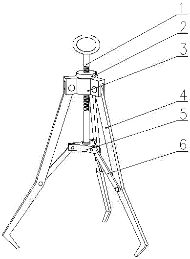
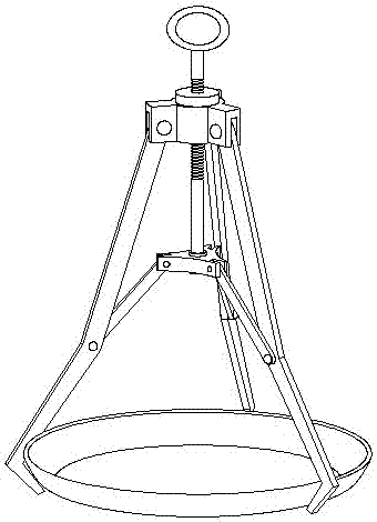
[0013] Such as figure 1 As shown, a kitchen bowl remover of the present invention includes a screw extraction mechanism and a bowl clamping mechanism, and the bowl clamping mechanism includes a claw connecting block 3, a claw 4, a pull rod connecting block 5 and a pull rod 6, Several claws 4 are evenly distributed around the claw connecting block, and the claws 4 can rotate around the installation pin on the claw connecting block 3, and the two ends of the pull rod 6 are respectively connected at the bending points of the claws 4 and the pull rod connection block 5; the screw extraction mechanism includes a screw handle 1 and a lock nut 2, the center of the claw connection block 3 is a through hole, and the screw handle 1 passes through the through hole of the claw connection block 3 It is fixedly connected with the pull rod connection block 5; the lock nut 2 is located on the screw handle 1 and matches the thread of the screw handle 1, and the lock nut 2 can be screwed on the...


PUM


Abstract

The invention discloses a bowl lifter for kitchens. The bowl lifter comprises a screw lifting mechanism and a bowl clamping mechanism; the bowl clamping mechanism comprises a clamping-jaw connecting block, clamping jaws, a pull-rod connecting block and pull rods; a plurality of clamping jaws are evenly distributed on the periphery of the clamping-jaw connecting block, the clamping jaws can rotate around mounting pin rolls on the clamping-jaw connecting block, and two ends of the pull rods are respectively connected to positions of bending points of the clamping jaws and the pull-rod connecting block; the screw lifting mechanism comprises a screw handle and a locking nut, a through hole is formed in the center of the clamping-claw connecting block, and the screw handle is fixedly connected with the pull-rod connecting block through the through hole of the clamping-jaw connecting block; the locking nut is located on the screw handle and is in threading fitness with the screw handle, and a nut can be tightly screwed in the clamping-jaw connecting block when a bowl is clamped through the jaws. When the screw handle is uplifted, the pull-rod connecting block drives one ends of the pull rods of the jaws to be upward while the other ends to pull the jaws to retract axially to have the bowl clamped, and the locking nut locks the pull rods to prevent the same from moving.

Description

technical field [0001] The invention relates to kitchen utensils, in particular to a kitchen bowl remover. Background technique [0002] Steaming is a wide range of cooking methods. In addition to steaming pans, steaming racks, and bowls, the cooking utensils involved in steaming in the kitchen must also have steamed bowls and pans in order to take out the hot dishes without burning your hands. Removed bowl remover. The structure of the existing tripod-shaped bowl remover is too simple and unreasonable. When the handle is lifted up to lift the bowl in use, the claws are forced to open outwards, and the other hand must be used to press down when operating. The claws are inconvenient to operate, and the claws of the bowl taker are easy to unhook and cause the bowls to fall. The bowl remover disclosed by the present invention is suitable for bowls with different circumference sizes. When the bowl is lifted upwards, the claws clamp the bowls in the direction of the axis under ...

Claims


Application Information

Patent Timeline
IPC IPC(8): A47J45/10
CPCA47J45/10
Inventor 叶泉清
Owner 叶泉清
Why Eureka
Try Eureka