
Method and system for establishing connection between base stations, configuration method and system

A technology between base stations and adjacent base stations, which is applied in the field of base station identification expansion configuration and the establishment of X2 interface connections between base stations, which can solve problems such as preempting base station addressing space, unable to find PCI configuration, and waste.

Active Publication Date: 2020-02-21
CHINA TELECOM CORP LTD
View PDF5 Cites 0 Cited by
  • Summary
  • Abstract
  • Description
  • Claims
  • Application Information

AI Technical Summary

Problems solved by technology

[0004] 1. If simply reducing the number of base station bits to increase the number of cell addresses, on the one hand, the address space of other base stations with a normal 20-bit address length may be seized, and some base station addresses may be adjusted
On the other hand, when the address space of the cell is underutilized, it will also bring a certain amount of waste.
[0005] 2. In the current protocol, MME can only recognize 20-bit addresses and 28-bit addresses. In order to expand the number of cells, the new base station address numbering method may be affected, and the core network needs to define a new identification method
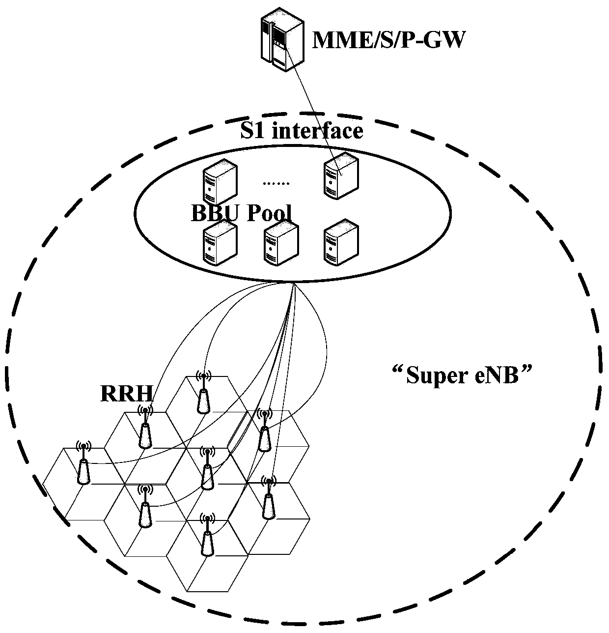
In addition, this phenomenon will also lead to the failure of the mechanism to prevent PCI confusion and conflicts because too many cells' PCI information is transmitted to the target base station, such as Figure 4 shown
The super cell has a large coverage area. According to the existing scheme, all cell configuration information is exchanged. For the neighboring cells of the super cell, it is found that it is impossible to find a suitable PCI for configuration.

Method used


Image

  • Method and system for establishing connection between base stations, configuration method and system
  • Method and system for establishing connection between base stations, configuration method and system
  • Method and system for establishing connection between base stations, configuration method and system

Examples


Embodiment Construction

[0071] The present invention will be described more fully hereinafter with reference to the accompanying drawings, in which exemplary embodiments of the invention are illustrated. The following will clearly and completely describe the technical solutions in the embodiments of the present invention with reference to the accompanying drawings in the embodiments of the present invention. Obviously, the described embodiments are only some, not all, embodiments of the present invention. Based on the embodiments of the present invention, all other embodiments obtained by persons of ordinary skill in the art without making creative efforts belong to the protection scope of the present invention. The technical solution of the present invention will be described in various aspects below in conjunction with various figures and embodiments.

[0072] The terms "first" and "second" in the following are only used for description and have no other special meanings.

[0073] Figure 5 It is...


PUM


Abstract

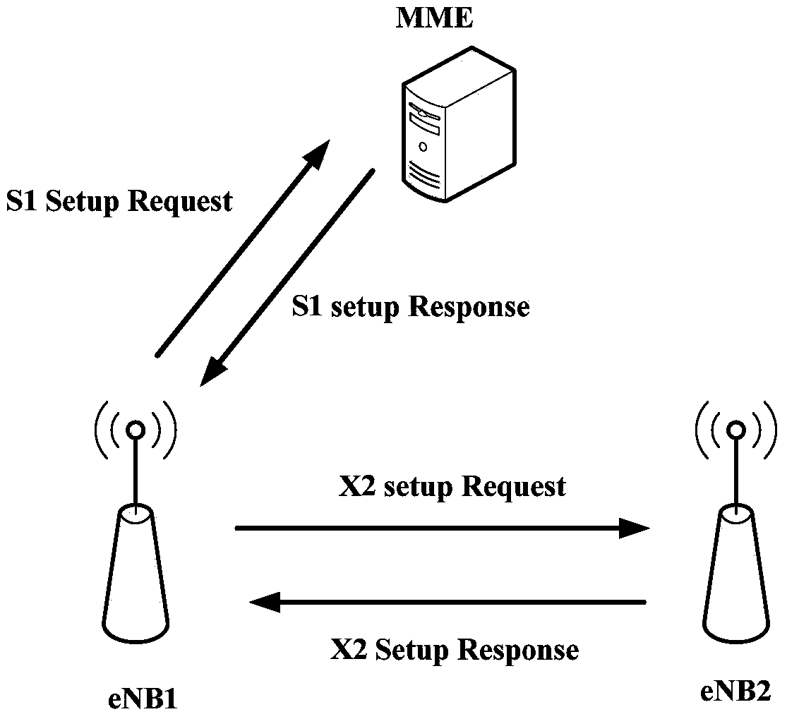
The invention discloses an inter-base-station X2 interface connection establishing method and system and a base station identifier expansion configuration method and system. The establishing method includes that a source base station extracts a basic base station identifier and an expansion base station identifier from an ECGI from preset configuration information and sends an identification request carrying the basic base station identifier and the expansion base station identifier to a core network; the source base station establishes X2 interface connection with an adjacent base station based on first base station identifier set information and an IP address in support of the base station belonging to an adjacent cell and sent back by the core network. According to the invention, automatic identification and configuration of cell identifiers of flexible lengths by the base station and the core network can be realized, manual intervention and maintenance cost in network deployment are reduced, current protocol process is put into reuse, backward compatibility is enhanced; problems of comparatively large future demand for cell address identifiers in BBU cells and address restrictions in a current standard are solved; and cell identifier addressing capacity is improved.

Description

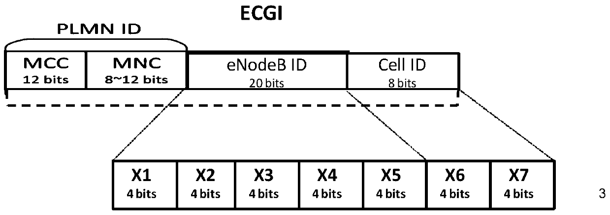
technical field [0001] The present invention relates to the field of communication technologies, and in particular to a method and system for establishing X2 interface connections between base stations, and a method and system for configuring base station identifier expansion and configuration. Background technique [0002] ECGI (E-UTRAN Cell Global Identifier, E-UTRAN cell global identifier) ​​is globally unique and consists of three parts: PLMN ID, eNodeB ID, and Cell ID. Such as figure 1 Therefore, ECGI can be used to identify a cell (or carrier sector), create base station and cell data, send the broadcast information to the terminal for network selection, assist SON (Self-Organized Networks, self-organizing network) functions and positioning services, and billing It works in scenarios such as distinguishing the place where the business occurs in the bill. PLMN ID (Public Land Mobile Network, public land mobile network) is the mobile network number, eNodeB (Evolved Nod...

Claims


Application Information

Patent Timeline
Patent Type & Authority Patents(China)
IPC IPC(8): H04W76/11
Inventor 许森刘悦朱雪田孙震强张光辉
Owner CHINA TELECOM CORP LTD
Learn More