
Safety detecting system for vehicle condition in operation state and using method

A technology for safety detection and operating status, applied in measuring devices, vehicle components, transportation and packaging, etc., can solve problems such as potential safety hazards, impact on safety and reliability, lack of detection capabilities, etc., and achieve flexible and convenient use and automatic operation High, the effect of improving safety and reliability

Active Publication Date: 2017-10-20
HENAN POLYTECHNIC
View PDF4 Cites 2 Cited by
  • Summary
  • Abstract
  • Description
  • Claims
  • Application Information

AI Technical Summary

Problems solved by technology

[0002] With the promotion and popularization of automobiles, automobiles have been widely used in the fields of home life, commercial operation, and logistics transportation. However, in the application, it is found that the current automobiles often only have the functions In order to achieve the purpose of improving the safety of vehicle operation, it is found that during the operation of the vehicle, the ambient temperature in the engine compartment, the hub temperature, The temperature of the brake system, the torque on the wheel bearing and the coaxiality between the wheel axle and the tire will have a serious impact on the safety and reliability of the vehicle operation. Operational safety has an extremely important impact, and the current vehicles lack effective detection capabilities for these vehicle condition information, so there is a great potential safety hazard in the operation of the vehicle. Therefore, it is urgent to develop a new Advanced vehicle operation safety detection system and detection method to meet the needs of actual use

Method used


Image

  • Safety detecting system for vehicle condition in operation state and using method
  • Safety detecting system for vehicle condition in operation state and using method
  • Safety detecting system for vehicle condition in operation state and using method

Examples


Embodiment Construction

[0020] In order to make the technical means, creative features, goals and effects achieved by the present invention easy to understand, the present invention will be further described below in conjunction with specific embodiments.

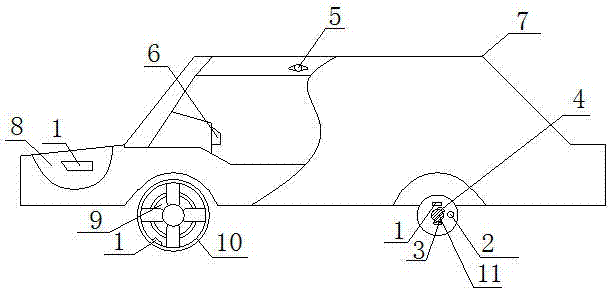
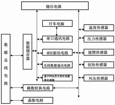
[0021] Such as figure 1 with 2 A vehicle condition safety detection system under the described running state comprises a temperature sensor 1, a pressure sensor 2, a swing sensor 3, a torque sensor 4, a wind pressure sensor 5 and a control circuit 6, and the control circuit 6 is connected to the temperature sensor 1 and the pressure sensor respectively. 2. The swing sensor 3, the torque sensor 4, and the wind pressure sensor 5 are electrically connected. Among them, several temperature sensors 1 are evenly distributed on the inner wall 8 of the engine room of the automobile 7, the rear surface of the brake disc 9 and the inner surface of the wheel hub 10. The pressure sensor 2 at least four, respectively uniformly distributed on the rear surface ...


PUM


Abstract

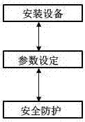
The invention relates to a safety detecting system for the vehicle condition in the operation state. The safety detecting system comprises a temperature sensor, a pressure sensor, a swing sensor, a torque sensor, an air pressure sensor and a control circuit. The control circuit is in electrical connection with the temperature sensor, the pressure sensor, the swing sensor, the torque sensor and the air pressure sensor. The control circuit is embedded in a console of a vehicle and is in electrical connection with a trip computer of the vehicle. A using method of the safety detecting system comprises three steps of equipment mounting, parameter setting and safety protecting and other steps. The safety detecting system is simple in structure, flexible and convenient to use and high in operation automation degree; the vehicle condition in the operation state of the vehicle can be effectively and continuously detected under the situation that the vehicle structure is not changed, accordingly potential safety hazards in vehicle operation are convenient to find timely and effectively, and the safety and reliability of vehicle operation are improved.

Description

technical field [0001] The invention relates to a vehicle condition safety detection system in a running state and a using method thereof, belonging to the technical field of automobiles. Background technique [0002] With the promotion and popularization of automobiles, automobiles have been widely used in the fields of home life, commercial operation, and logistics transportation. However, in the application, it is found that the current automobiles often only have the functions In order to achieve the purpose of improving the safety of vehicle operation, it is found that during the operation of the vehicle, the ambient temperature in the engine compartment, the hub temperature, The temperature of the brake system, the torque on the wheel bearing and the coaxiality between the wheel axle and the tire will have a serious impact on the safety and reliability of the vehicle operation. Operational safety has an extremely important impact, and the current vehicles lack effecti...

Claims


Application Information

Patent Timeline
Patent Type & Authority Applications(China)
IPC IPC(8): B60R16/023G01D21/02
CPCB60R16/0232G01D21/02
Inventor 李林燕姬虹宋东方尹冠飞王红伟
Owner HENAN POLYTECHNIC
Learn More