Table-foot structure of rack

A table foot and rack technology, applied in the field of table foot structure of racks, can solve problems such as affecting production safety and efficiency, affecting shoe buttons, affecting production efficiency, etc., achieving convenient operation, solving unstable placement and simple structure. Effect

Inactive Publication Date: 2017-10-20
ANHUI NUOHAO SHOES
View PDF0 Cites 0 Cited by
  • Summary
  • Abstract
  • Description
  • Claims
  • Application Information

AI Technical Summary

Problems solved by technology

However, due to the structural design of the pulley itself, the equipment installed with the pulley is prone to shaking and instability during use, which affects the safety and efficiency of production. There are pulleys on the feet, which is very convenient to move, but when the button is buckled, when the pedal moves the driving lever, the pulley will shake, which will affect the hand-held shoes and the stable button, and affect the production efficiency

Method used


Image

  • Table-foot structure of rack

Examples


Embodiment 1

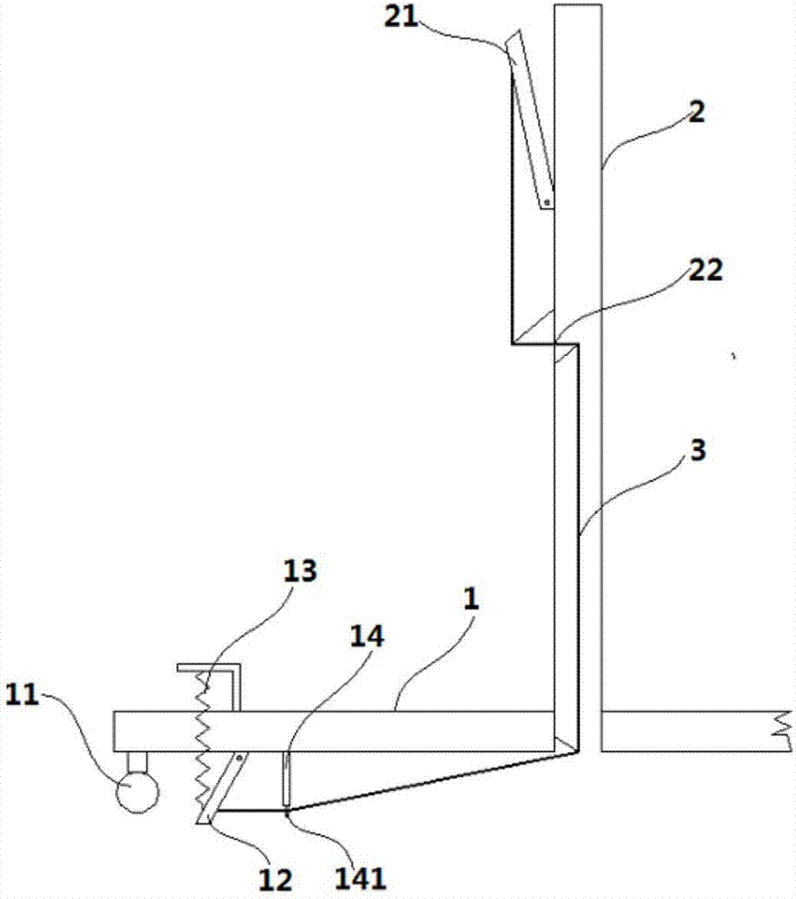
[0014] A table leg structure for a rack, such as figure 1 As shown, it includes a support rod 2 fixed on the top of the table leg 1. Four pulleys 11 are installed at the bottom of the table leg 1. A leg 12 is arranged beside the pulley 11. The length of the leg 12 is greater than the height of the pulley 11. The upper end of the leg 12 is It is fixed on the bottom of the table leg 1 by means of a hinge, and the leg 12 is tightened and laterally attached to the bottom of the table leg 1 by the spring 13 fixed on the table leg 1, and a pole is provided on the bottom of the table leg 1 next to the leg 12 14. The bottom of the pole 14 is provided with a ring 141, one end of the rope 3 passes through the ring 141 and is fixed on the foot 12, and the other end of the rope 3 is fixed on the handle 21 on the support rod 2, and the handle 21 passes through the The mode of hinge is fixed on support bar 2, and rope 3 is tensioned state, pulls pull handle 21 upwards, and supporting foot ...


PUM


Abstract

The invention discloses a table foot structure of a frame, which comprises a support rod fixed on the upper part of the table foot, four pulleys are installed on the bottom of the table foot, and a support foot is arranged beside the pulley, the length of the support foot is greater than the height of the pulley, and the length of the support foot is greater than the height of the pulley. The upper end is fixed on the bottom of the table leg by means of a hinge, and the leg is tightened and horizontally fitted on the bottom of the table leg through the spring fixed on the table leg. There is a ring, one end of the rope passes through the ring and is fixed on the support foot, the other end of the rope is fixed on the pull handle on the support rod, the pull handle is fixed on the support rod by a hinge, and the rope is in a tight state. The invention has the advantages of simple structure, convenient operation and strong practicability, effectively solves the problem of unstable placement and easy shaking of the frame with pulleys, and is simple to manufacture and low in cost, has good technical effect, and is worthy of popularization and use.

Description

technical field [0001] The invention relates to a table leg structure of a rack. Background technique [0002] There are a lot of shoe-making equipment in the workshop of the shoe-making factory. The table legs of the racks of these equipment are generally in direct contact with the ground. When the equipment needs to be moved, manual labor is required to move the equipment. There is a technology to install pulleys at the bottom of the table legs. When the equipment needs to be moved, the equipment can be directly pushed to move, which is very convenient and labor-saving. However, due to the structural design of the pulley itself, the equipment installed with the pulley is prone to shaking and instability during use, which affects the safety and efficiency of production. There are pulleys on the feet, which is very convenient to move, but when the button is pressed, the pulley will shake when the pedal moves the driving lever, which will affect the hand-held shoes and the...

Claims


Application Information

Patent Timeline
IPC IPC(8): A43D119/00
CPCA43D119/00
Inventor 胡芳
Owner ANHUI NUOHAO SHOES
Why Eureka
Try Eureka