Welding device

A welding device and welding machine technology, applied in the direction of auxiliary equipment, welding equipment, auxiliary welding equipment, etc., can solve the problems of inconvenient use of the welding machine, loose plug joints, electric shock accidents, etc., to improve the safety of power supply and the stability of plug connection Sexuality, preventing loosening of plug connections, and preventing electric shock accidents

Inactive Publication Date: 2017-10-17
何华勇
View PDF12 Cites 0 Cited by
  • Summary
  • Abstract
  • Description
  • Claims
  • Application Information

AI Technical Summary

Problems solved by technology

[0002] Welding machines are often used in the field of electric welding. Welding machines need to be powered and plugged in before they can be used. Because welding machines require high voltage, they are generally equipped with power distribution boxes. However, existing power distribution boxes are generally directly connected to the mains. Moreover, the conductive part of the internal socket is set relatively outside, which is very easy to cause electric shock accidents under human careless touch, and there is a large potential safety hazard. At the same time, the power supply cable used by the welding machine has a large weight , and the electric welding machine does not set any locking structure during the plugging process. Under the influence of the power supply cable due to its own weight or pulling factors, it is very easy to cause the plug connector to loosen, resulting in power supply interruption, which brings great harm to the normal use of the welding machine. inconvenient

Method used


Image

  • Welding device
  • Welding device
  • Welding device

Examples


Embodiment Construction

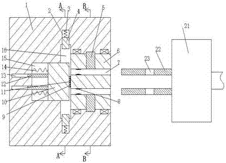
[0026] Combine below Figure 1-7 The present invention will be described in detail.

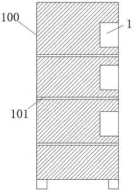
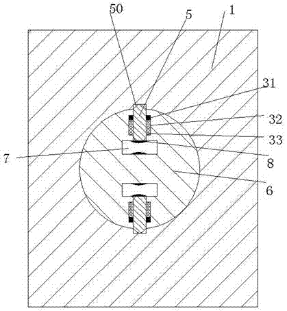
[0027] refer to Figure 1-7 , according to an embodiment of the present invention, a welding device includes a distribution box 100 and an electrical connector 21 connected to the welding machine. In the distribution box 100, there are at least one set of The electrical connection seat 1, the electrical connection seat 1 is provided with a transfer hole with the opening facing the right, and an adapter 6 is rotatably installed in the transfer hole, and the upper and lower sides of the transfer member 6 are equal A plugging groove 7 communicating with the left and right is provided, and an electric link piece 8 is fixedly installed in the plugging groove 7, and a wear-resistant sheet 11 is fixedly installed in the middle of the left end surface of the adapter 6, and the wear-resistant sheet 11 The left end face is provided with an empty hole, and the electrical connection seat 1 is located a...


PUM


Abstract

Provided is a welding device. The welding device comprises a distribution box and an electric connecting head which is connected with a welding machine. At least more than one group of electric connecting bases is arranged in the distribution box and is separated up and down through separation plates. Transferring holes with rightward through openings are formed in the electric connecting bases, and transferring pieces are rotatably installed in the transferring holes. Left-and-right intercommunicated plugging grooves are formed in the transferring pieces equivalently up and down, and electric connecting pieces are fixedly installed in the plugging grooves. Wear-proof pieces are fixedly installed in the middles of the left end faces of the transferring pieces, and empty holes are formed in the left end faces of the wear-proof pieces. Ring connecting grooves are formed in the part, located at the left ends of the transferring holes, of the electric connecting bases. Middle grooves are formed in the middles of the left ends of the ring connecting grooves. Sliding connecting pieces capable of sliding left and right are installed in the middle grooves. Plug pins are fixedly installed in the middles of the right end faces of the sliding connecting pieces. Crescent grooves located in the rear parts above the sliding connecting pieces and located in the front parts below the sliding connecting pieces are formed in the end walls of the ring connecting grooves. Pushing grooves extending up and down are formed in the end walls of the ring connecting grooves equivalently up and down. The pushing grooves communicate with the crescent grooves, and electricity connecting blocks are installed in the pushing grooves in a sliding connecting mode.

Description

technical field [0001] The invention relates to the technical field of welding, in particular to a welding device. Background technique [0002] Welding machines are often used in the field of electric welding. Welding machines need to be powered and plugged in before they can be used. Because welding machines require high voltage, they are generally equipped with power distribution boxes. However, existing power distribution boxes are generally directly connected to the mains. Moreover, the conductive part of the internal socket is set relatively outside, which is very easy to cause electric shock accidents under human careless touch, and there is a large potential safety hazard. At the same time, the power supply cable used by the welding machine has a large weight , and the electric welding machine does not set any locking structure during the plugging process. Under the influence of the power supply cable due to its own weight or pulling factors, it is very easy to cause...

Claims


Application Information

Patent Timeline
Patent Type & Authority Applications(China)
IPC IPC(8): B23K37/00
CPCB23K37/00
Inventor 何华勇
Owner 何华勇
Why Eureka
Try Eureka