
A high-power circulator and its anti-microdischarge design method

A circulator and high-power technology, applied in the field of circulator and its anti-micro-discharge design, can solve the problems of increased loss and great influence on the electrical performance of microwave components, achieve small structure size, avoid low-pressure discharge, and micro-discharge thresholds The effect of power increase

Active Publication Date: 2019-05-24
XIAN INSTITUE OF SPACE RADIO TECH
View PDF4 Cites 0 Cited by
  • Summary
  • Abstract
  • Description
  • Claims
  • Application Information

AI Technical Summary

Problems solved by technology

This type of method leads to a general increase in loss and has a great impact on the electrical properties of microwave components

Method used


Image

  • A high-power circulator and its anti-microdischarge design method
  • A high-power circulator and its anti-microdischarge design method
  • A high-power circulator and its anti-microdischarge design method

Examples


Embodiment 1

[0046] Example 1: High-power Y-junction circulator and its anti-micro-discharge design method

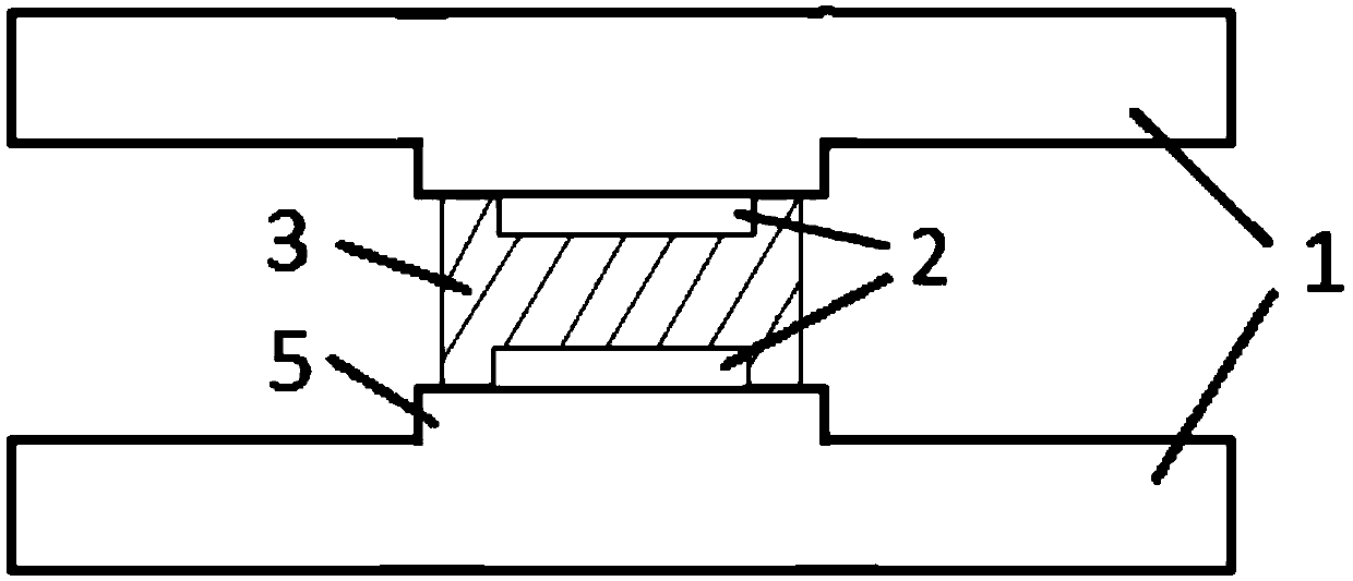
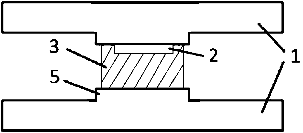
[0047] Such as Figure 5 As shown, the high-power circulator includes a metal cavity 1, a ferrite gyromagnetic substrate 2, and a dielectric card slot 3. A metal matching table 5 and a positioning groove 4 are processed on the metal cavity 1, wherein the ferrite The body gyromagnetic substrate 2 is located in the media card slot 3. The media card slot 3 clamps the ferrite gyromagnetic substrate 2 in the metal cavity 1; the upper cover of the metal cavity 1 is installed on the base, and the upper cover is connected with A cavity is formed between the bases. The cavity includes a central area loaded with ferrite gyromagnetic substrate 2 and three ports. The three ports are respectively connected to external circuits. When a certain frequency of electromagnetic waves is incident on one port, the electromagnetic waves It is output by the next port of the loop, and has a certain degree of ...


PUM


Abstract

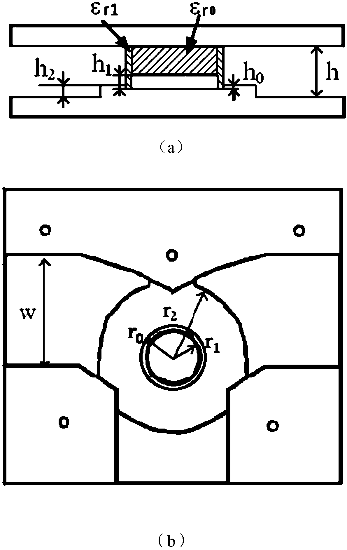
The invention discloses a high-power circulator. The high-power circulator comprises a metal cavity (1), a ferrite gyromagnet substrate (2) and a medium neck (3), wherein the metal cavity (1) comprises an upper cover and a base, grooves are formed in the upper cover and the base at mirror symmetry positions, the upper cover is mounted on the base, and a cavity is formed between the upper cover and the base; the ferrite gyromagnet substrate (2) is positioned inside the medium neck (3); the medium neck (3) is mounted in the cavity of the metal cavity (1) and is positioned between the groove of the upper cover and the groove of the base, so that the ferrite gyromagnet substrate (2) clings to the metal cavity (1). According to the method disclosed by the invention, the strongest field intensity is firstly concentrated on a gyromagnet substrate area through initial electrical performance design optimization, then multilayer concentric medium circular rings are loaded in the area to form the medium neck with dielectric constant of space variation, then electrical performance optimization and microdischarge simulating optimization are further carried out, and microdischarge electron orbit blocking is realized under the premise of meeting actual electrical performance requirement, so that the microdischarge threshold value power is effectively promoted.

Description

Technical field [0001] The invention relates to a circulator and its anti-micro-discharge design method. Background technique [0002] The high micro-discharge risk of spacecraft's high-power microwave components is a key factor affecting the long life and high reliability of the spacecraft's payload, and it is also the largest single-point failure link of satellites under high-power applications. [0003] Traditional microdischarge suppression methods are mainly divided into two categories: physical suppression methods and chemical suppression methods. Among them, the physical suppression method is mainly to increase the micro-discharge threshold by increasing the distance between the metal surfaces at the maximum electric field intensity of the microwave component. For spacecraft microwave components, due to the strict control of their volume and quality, the method of increasing the microdischarge threshold by increasing the physical size has great limitations. At the same tim...

Claims


Application Information

Patent Timeline
Patent Type & Authority Patents(China)
IPC IPC(8): H01P1/383H01P11/00
CPCH01P1/383H01P11/00
Inventor 李韵崔万照贺永宁
Owner XIAN INSTITUE OF SPACE RADIO TECH
Learn More