Static core code restraining lock

A code lock and static core technology, applied in the field of anti-theft locks, can solve problems such as ineffective anti-theft

Pending Publication Date: 2017-10-13
赵兰旺
View PDF0 Cites 0 Cited by
  • Summary
  • Abstract
  • Description
  • Claims
  • Application Information

AI Technical Summary

Problems solved by technology

At present, the tumbler locks widely used by people cannot effectively prevent theft at all due to the failure to completely get rid of the above design defects.

Method used


Image

  • Static core code restraining lock
  • Static core code restraining lock
  • Static core code restraining lock

Examples


Embodiment Construction

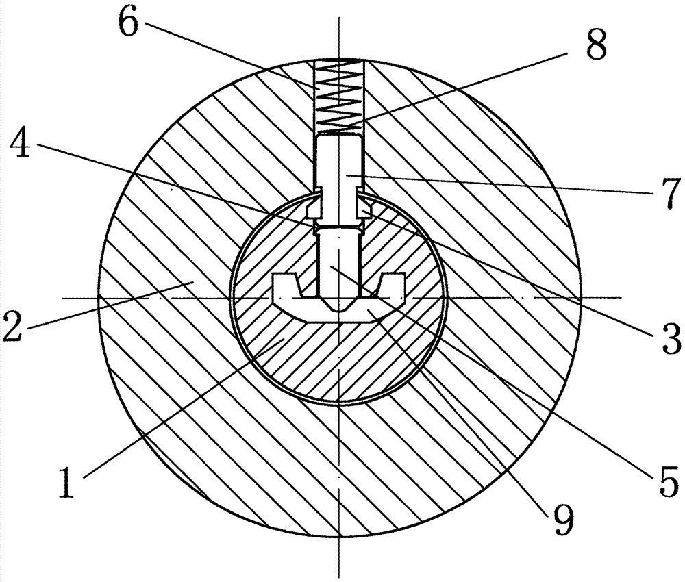
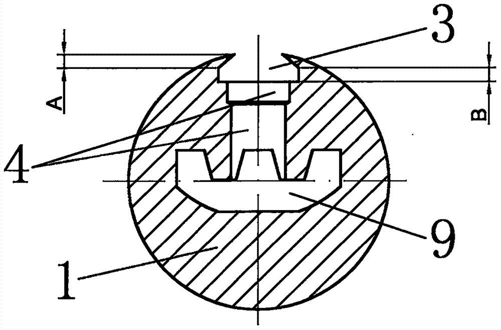
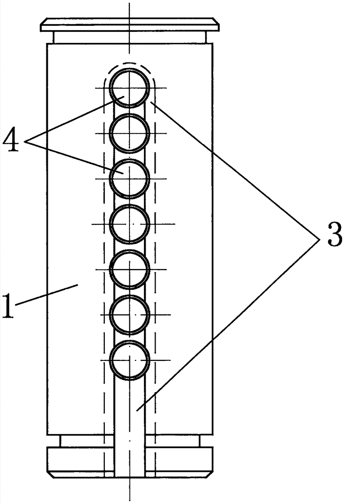
[0013] A static core trip lock, such as Figure 1 to Figure 3 shown. It consists of a lock cylinder 1, a lock cylinder cover 2, a trip code groove 3, a lock cylinder pin hole 4, a lock core pin pin 5, a lock sleeve pin hole 6, a lock sleeve second layer pin pin 7 and a pin spring 8. The lock core is located in the lock core sleeve, and the key groove 9 is located at the front end of the lock core, and the key groove type is not limited. The pin spring is located in the lock core sleeve. There are one or two layers of pins from the front end of the pin spring to the key slot. The key teeth and the one or two layers of pins cooperate to realize the opening and closing of the lock body.

[0014] Such as figure 2 and image 3 As shown, the trip code groove is located at the outer end of the entire row of pinholes in the lock cylinder, parallel to the key slot of the lock cylinder, and runs through all the pinholes along the center line of the entire row of pinholes. Horseshoe...


PUM


Abstract

The invention belongs to a static core code restraining lock of a pure mechanical elastomer structure. The static core code restraining lock comprises a lock core, a lock core sleeve, a code restraining groove, lock core elastomer holes, lock core first layer elastomers, a lock sleeve elastomer hole, lock sleeve second layer elastomers, an elastomer spring and a lock core key groove, wherein the code restraining groove of which the interior is wide, the exterior is narrow and the section is special shape horseshoe-shaped (trapezoid combined with rectangle) is additionally formed in the outer ends of the lock core entire row elastomer holes, is parallel to the lock core key groove, and penetrates through all the elastomer holes along center lines of the entire row elastomer holes; the lock core elastomer holes and the lock core first layer elastomers are designed as T-shaped step-shaped; and the lock sleeve second layer elastomers are designed as I shape of which the two ends are thick and the middle is thin. According to the static core code restraining lock, through the structural design, a user is only allowed to insert a key when the lock core is in the static state to release locking corresponding to all the elastomers to open the lock, if the user does not have the key, rotary force (a must for technical lock opening) applied to the lock core in the lock core opening direction by any unlocking tools triggers the technical unlocking prevention function preset between the code restraining groove and the second layer elastomers, unlocking action is prohibited by virtue of the static core, technical opening aimed at mechanical elastomer locks can be effectively restrained, and a super excellent burglary prevention effect is achieved.

Description

technical field [0001] The invention belongs to an anti-theft lock. Background technique [0002] In the traditional lock, the front end of the lock cylinder is the key entry port, the key slot is set inside the lock cylinder, and the side end of the slot is provided with pinholes. , There is a layer of marbles in the pin hole of the lock cylinder, a second layer of pins is provided in the corresponding layer of pinholes in the lock core sleeve, the rear end of the second layer of pins is provided with a spring to press the first and second layers of pins, the outer end of the spring is closed, and the rear end of the lock cylinder is closed. The end is connected to the opening pin, which is used to toggle the dead bolt to open the lock. When the tooth code on the key makes the gap between the pins on the first layer and the pins on the second layer just lie on the adjacent interface between the lock cylinder and the lock cylinder sleeve, the lock cylinder will get rid of t...

Claims


Application Information

Patent Timeline
IPC IPC(8): E05B27/10E05B15/14E05B15/00
CPCE05B27/0007E05B27/0017E05B27/0057E05B27/10
Inventor 赵兰旺陈乃刚赵立柱
Owner 赵兰旺
Why Eureka
Try Eureka