Product packaging machine and using method thereof

A product packaging and product technology, which is applied in the field of gunpowder and explosive charge, can solve the problems of low quality of detection and marking, difficult fully automated operation, low work efficiency, etc., and achieves high precision, compact structure, and high labor intensity. Effect

Pending Publication Date: 2017-09-29
BEIJING AEROSPACE SANFA HIGH TECH
View PDF7 Cites 2 Cited by
  • Summary
  • Abstract
  • Description
  • Claims
  • Application Information

AI Technical Summary

Problems solved by technology

[0002] In the process of charging gunpowder or explosives, the product needs to be inspected, marked, and packed. The existing technology is to manually inspect, print, and pack, which is not only labor-intensive, but also has low work efficiency and low quality of inspection and marking. , and it is difficult to realize the fully automatic operation of the charging process

Method used


Image

  • Product packaging machine and using method thereof
  • Product packaging machine and using method thereof
  • Product packaging machine and using method thereof

Examples


Embodiment Construction

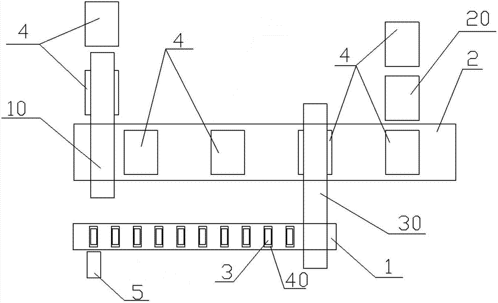
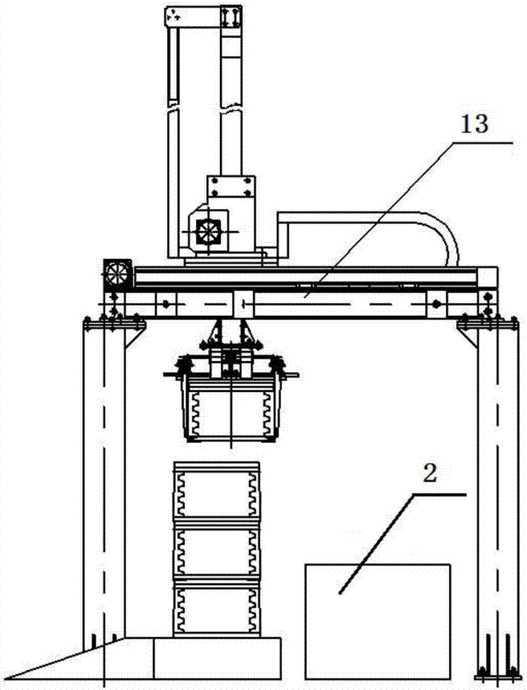
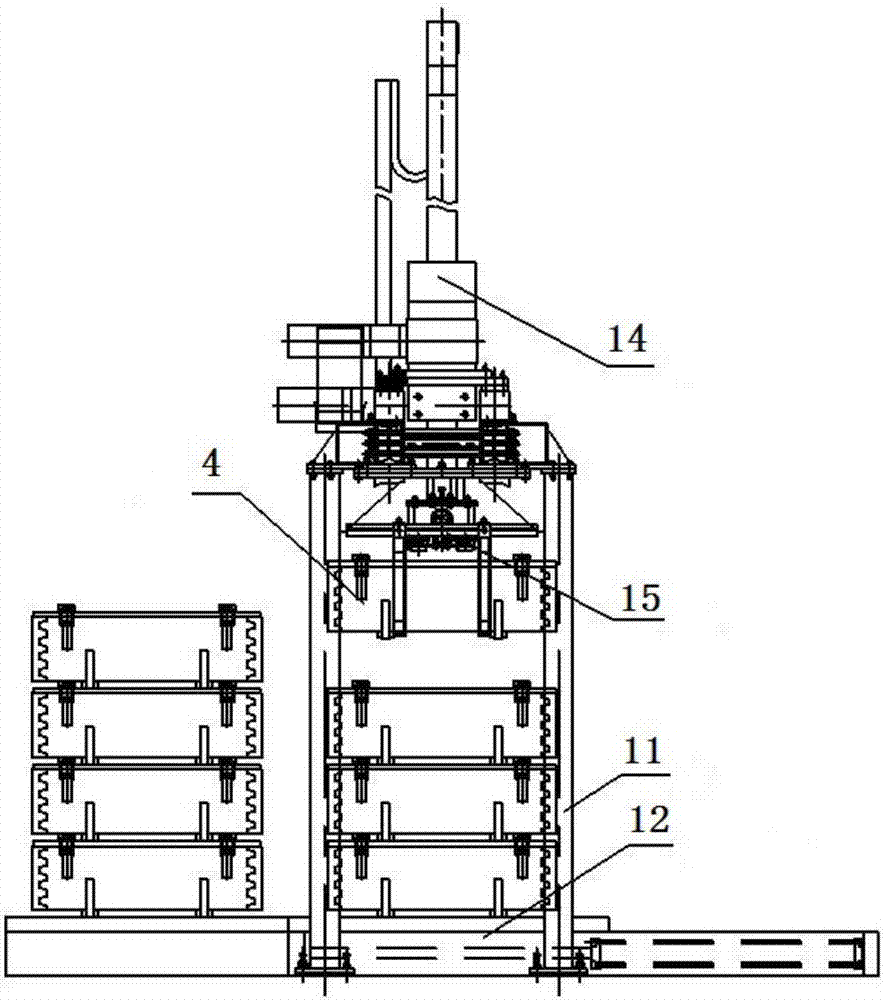
[0025] Such as Figure 1-7 As shown, a product packaging machine includes: an assembly detection conveyor line 1, a packing box conveyor line 2, a product detection device 5, a case loading machine 10, a case lowering stacker 20, a case packing machine 30 and an assembly detection conveyor line holder Board tooling 40; the assembly detection conveying line 1 and the packing box conveying line 2 are arranged in parallel in the horizontal direction, the box loading machine 10 is arranged at the initial end of the packing box conveying line 2, and the longitudinal beam of the box loading frame 11 It is arranged on both sides of the packing case conveying line 2, the lower case stacker 20 is arranged at the end of the packing case conveying line 2 and is located on one side of the packing case conveying line 2, and the packing case 30 is set Between the upper box machine 10 and the lower box stacker 20, the assembly detection conveyor line 1 and the packaging box conveyor line 2 a...


PUM


Abstract

Provided is a product packaging machine. An assembly detecting conveying line and a packaging box conveying line are parallelly arranged. A box feeding machine is arranged at the initial end of the packaging box conveying line. Longitudinal beams of a box feeding machine frame are arranged at the two sides of the packaging box conveying line. A box discharging stacker is arranged at the tail end of the packaging box conveying line and is located at one side of the packaging box conveying line. A box filling machine is arranged between the box feeding machine and the box discharging stacker. The assembly detecting conveying line and the packaging box conveying line are arranged between two longitudinal beams of a box filling machine frame. A product detecting device is arranged at the initial end of the assembly detecting conveying line and is located at one side of the assembly detecting conveying line. Packaging boxes are placed on the packaging box conveying line. Assembly detecting conveying line carrying plate tools are placed on the assembly detecting conveying line. Products are placed on the assembly detecting conveying line carrying plate tools.

Description

technical field [0001] The invention relates to the field of gunpowder and explosive charging, in particular to a product packaging machine and a method for using the same. Background technique [0002] In the process of charging gunpowder or explosives, the product needs to be inspected, marked, and packed. The existing technology is to manually inspect, print, and pack, which is not only labor-intensive, but also has low work efficiency and low quality of inspection and marking. , and it is difficult to realize the fully automatic operation of the charging process. Contents of the invention [0003] The technical problem of the present invention is: to overcome the deficiencies of the prior art, and provide a product packaging machine and its use method. [0004] The technical solution of the present invention is: a product packaging machine, including: an assembly detection conveyor line, a packaging box conveyor line, a product detection device, a box loading machine,...

Claims


Application Information

Patent Timeline
IPC IPC(8): B65B43/46B65B57/10B65B5/08B65G57/20
CPCB65B5/08B65B43/46B65B57/10B65G57/20
Inventor 王慕雪武金泉周培好
Owner BEIJING AEROSPACE SANFA HIGH TECH
Why Eureka
Try Eureka