
Error-compensated direct digital modulation device

A technology of digital modulation and error compensation, applied in the field of providing error-compensated radio frequency signals based on digital baseband signals, which can solve problems such as reducing the usable operating distance of transceivers, increasing noise levels, and violating spectrum emission requirements or system specifications

Active Publication Date: 2017-09-26
HUAWEI TECH CO LTD
View PDF9 Cites 4 Cited by
  • Summary
  • Abstract
  • Description
  • Claims
  • Application Information

AI Technical Summary

Problems solved by technology

These accuracy degrading mechanisms additionally cause the noise level to increase
This can be problematic especially outside the spectrum of the desired transmitted signal, as the accuracy degradation mechanism can cause violations of spectrum emission requirements or system specifications
Specifically, the receive band of a frequency domain duplex (FDD) system is a problematic region of the spectrum when the receiver is insensitive, reducing the usable operating range of the transceiver

Method used


Image

  • Error-compensated direct digital modulation device
  • Error-compensated direct digital modulation device
  • Error-compensated direct digital modulation device

Examples


Embodiment Construction

[0085] In the following detailed description, reference is made to the accompanying drawings, which are a part hereof, and which illustrate, by way of illustration, specific aspects in which the invention may be practiced. It is to be understood that other aspects may be utilized and structural or logical changes may be made without departing from the scope of the present invention. Therefore, the following detailed description is not to be taken in a limiting sense, and the scope of the invention is defined by the appended claims.

[0086] It should be understood that comments made in connection with the described method may also apply equally to the corresponding apparatus or system for performing the described method and vice versa. For example, if a particular method step is described, the corresponding device may include means for performing the described method step, even if such means are not explicitly depicted or illustrated in the figures. Furthermore, it is to be u...


PUM


Abstract

The disclosure relates to an error-compensated direct digital modulation device (800), including: a direct digital radio frequency modulator (DDRM) (801), configured to generate a radio frequency (RF) signal (804) based on a modulation of a digital baseband signal (802); an error estimator (803) configured to determine an error signal (806) resulting from a deviation based on the generated RF signal (804) and a representation of the digital baseband signal (802); and an error compensator (805) configured to subtract the error signal (806) from the RF signal (804) to provide an error compensated RF signal (808).

Description

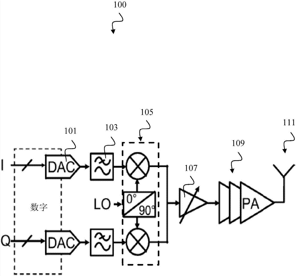
technical field [0001] The present invention relates to an error-compensated direct digital modulation device (DDRM) and a method for providing an error-compensated radio frequency (RF) signal based on a digital baseband signal. Background technique [0002] A direct digital RF modulator is a wireless transmitter circuit that modulates a digital baseband signal directly onto the RF carrier frequency. This is done by multiplying the baseband signal by a signal containing strong frequency components at the desired RF frequency (also known as a local oscillator). [0003] figure 1 A conventional quadrature upconverter chain 100 is illustrated. In most modern transmitters, the starting point for the digital representation is the baseband data (I, Q). The digital baseband data is converted into an analog equivalent signal by a baseband digital-to-analog converter (Digital-to-Analog converter, DAC) 101 . This is followed by a reconstruction filter 103, which is then used to cl...

Claims


Application Information

Patent Timeline
IPC IPC(8): H04L27/36H03M1/08H04L25/03H04B1/30H03M1/66H03M1/06G06F1/06
CPCH03M1/1047H03M1/66H04B1/123H04L25/03H04L27/122H04L27/368G06F1/06H03M1/06H03M1/0854H04B1/30H04B1/0007H04L27/2627
Inventor 彼得·帕尔默斯尼尔斯·克里斯多夫斯帕特里克·万德纳麦勒乔纳斯·桑姆森科恩·科内利森索菲亚·华帝
Owner HUAWEI TECH CO LTD
Learn More