
A metal hydride hydrogen storage device and working method

A hydride and hydrogen storage technology, which is applied in the direction of container filling method, container discharge method, container structure installation device, etc., can solve the problem that the rate of hydrogen filling and discharging cannot be effectively controlled, the device is difficult to disassemble and maintain, and the edge cannot be realized. Charge side discharge and other issues to achieve the effect of preventing gas overflow, simple design and manufacture, and convenient maintenance

Active Publication Date: 2019-02-01
JIANGSU UNIV OF SCI & TECH
View PDF8 Cites 0 Cited by
  • Summary
  • Abstract
  • Description
  • Claims
  • Application Information

AI Technical Summary

Problems solved by technology

Although this device can prevent the accumulation of hydrogen storage metal powder and the decline of hydrogen storage capacity during the hydrogen storage process, the device is simple but difficult to disassemble and maintain; although the hydrogen storage capacity is considerable, the rate of hydrogen charging and discharging cannot be effectively controlled; hydrogen in and out Only using the same channel greatly reduces the rate of charging and discharging hydrogen, especially when there is sufficient hydrogen, it is impossible to realize the function of charging and discharging at the same time

Method used


Image

  • A metal hydride hydrogen storage device and working method
  • A metal hydride hydrogen storage device and working method
  • A metal hydride hydrogen storage device and working method

Examples


Embodiment Construction

[0032] In order to make the purpose, technical solution and advantages of the present invention more clear, the present invention will be further described in detail below in conjunction with the accompanying drawings and embodiments. It should be understood that the specific embodiments described here are only used to explain the present invention, not to limit the present invention.

[0033] The directional terms mentioned in the present invention, such as "up", "down", "front", "back", "left", "right", "inside", "outside", "side", etc., are for reference only Attached directions. Therefore, the use of directional terms is used to illustrate and understand the present invention, but not to limit the present invention.

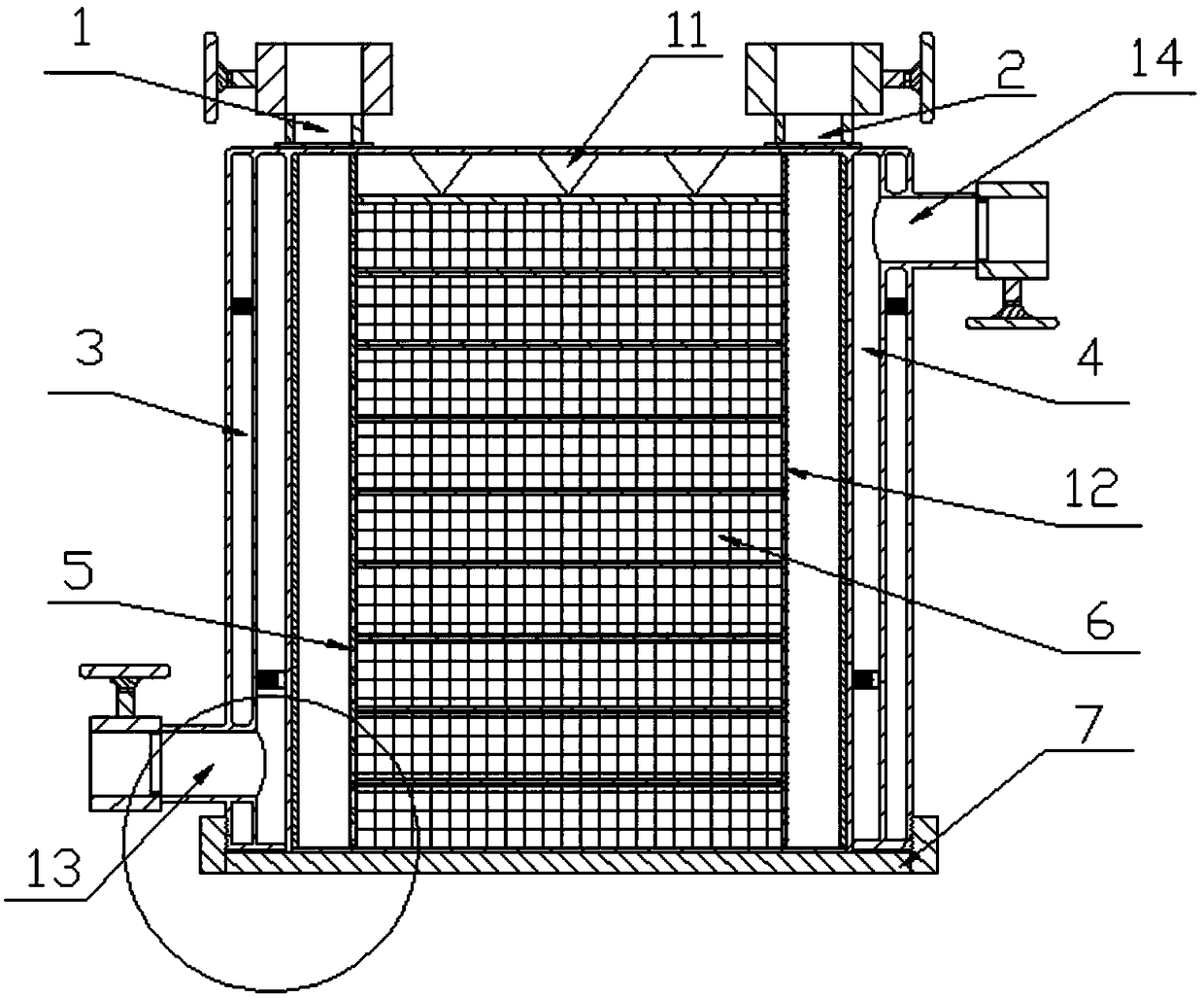
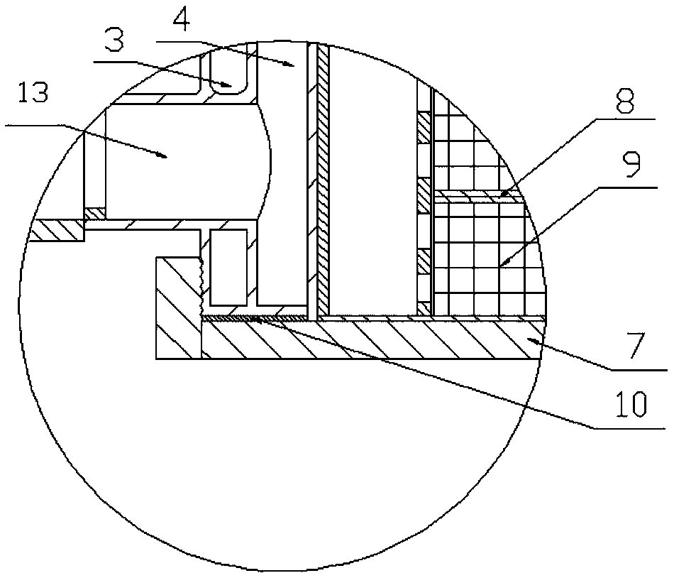
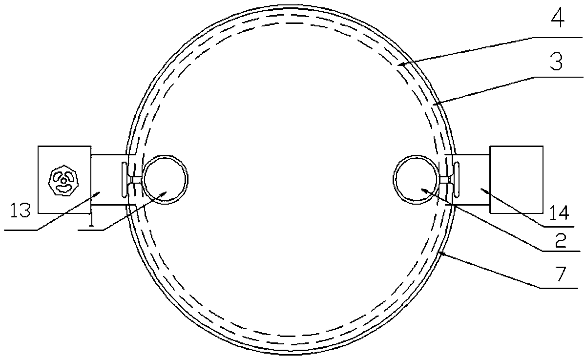
[0034] Such as figure 1 and figure 2 As shown, it is a metal hydride hydrogen storage device of the present invention, which is composed of a hydrogen storage cylinder 6, a heat exchange layer 4, a heat insulation layer 3, a metal grid 9, a metal partitio...


PUM


Abstract

The invention discloses a metal hydride hydrogen storage device. A barrel-shaped body with a downward opening is formed by sleeving a small-diameter part, a medium-diameter part and a large-diameter part in the mode that a gap is formed between every two of the parts, wherein a cavity formed by the small-diameter part is used as a hydrogen storage barrel, a sealed annular cavity which is composed by the first gap formed between the small-diameter part and the medium-diameter part is used as a heat exchange layer, and a sealed annular cavity which is composed by the second gap formed between the medium-diameter part and the large-diameter part is used as a heat insulating layer; a water inlet communicating with the heat exchange layer is formed in the upper end of the barrel wall of the barrel-shaped body through a pipeline, and a water outlet communicating with the heat exchanger layer is formed in the lower end of the barrel wall of the barrel-shaped body through a pipeline; an air inlet hole and an air outlet hole are symmetrically formed in the position, tightly attached to the inner wall of the hydrogen storage barrel, of the top of the barrel-shaped body, porous steel pipes penetrating through the hydrogen storage barrel are arranged in the air inlet hole and the air outlet hole correspondingly, and the walls of the porous steel pipes are coated with breathable films; a barrel cover is connected to the lower end of the barrel-shaped body; and a plurality of hydrogen storage unit layers are arranged in the hydrogen storage barrel through metal partition plates. The metal hydride hydrogen storage device is simple in structure, capable of controlling hydrogen absorption and release easily, high in hydrogen storage density, low in hydrogen storage pressure, safe, reliable and convenient to disassemble, assemble and maintain.

Description

technical field [0001] The patent of the present invention relates to a metal hydride hydrogen storage device, in particular to the structural design of the metal hydride hydrogen storage device, the internal arrangement of the metal hydride and the thermal management of hydrogen charging and discharging of the device. Background technique [0002] At present, hydrogen storage technology is divided into two categories, namely physical method and chemical method. Metal hydride hydrogen storage uses hydrogen to react with metals to form metal hydrides for storage, and releases hydrogen under certain environmental conditions. Hydrogen can react with many metals to form metal hydrides. These alloys will absorb a large amount of hydrogen to form metal hydrides under a certain temperature and pressure environment. At the same time, the reaction is very reversible. After reducing the pressure or increasing the temperature, it will A reversible reaction occurs, thereby releasing hy...

Claims


Application Information

Patent Timeline
Patent Type & Authority Patents(China)
IPC IPC(8): F17C11/00F17C13/00F17C13/06
CPCF17C11/005F17C13/00F17C13/001F17C13/06F17C2201/0119F17C2201/032F17C2201/056F17C2203/037F17C2205/0311F17C2221/012F17C2223/0123F17C2270/05Y02E60/32
Inventor 杨兴林王娜娜冯娟赵丹陈建树
Owner JIANGSU UNIV OF SCI & TECH
Learn More