Organic light-emitting display panel and display device

A light-emitting display, organic technology, applied in the direction of organic semiconductor devices, static indicators, instruments, etc., can solve the problems of uneven brightness of display devices, low aperture ratio of display devices, small cross-sectional size, etc., and achieves reduced attenuation and improved display. Brightness, the effect of increasing the aperture ratio

Active Publication Date: 2017-09-22
WUHAN TIANMA MICRO ELECTRONICS CO LTD
View PDF5 Cites 19 Cited by
  • Summary
  • Abstract
  • Description
  • Claims
  • Application Information

AI Technical Summary

Problems solved by technology

[0004] Since the power signal conducting wire 1 has a large number and a small cross-sectional size, it has a relatively large resistance. Therefore, in the direction from terminal a to terminal b, the current on the power signal conducting wire 1 gradually decreases, which means One situation will make the brightness of the b-end of the display device significantly lower than the brightness of the a-end, resulting in uneven brightness of the display device
[0005] On the other hand, if figure 2 Shown is a schematic diagram of the structure of the display panel. Since the anode via hole needs to be provided in the display panel, the area A where the anode via hole is located will block a part of the display area 2 of the display device, resulting in a low aperture ratio of the display device.

Method used


Image

  • Organic light-emitting display panel and display device
  • Organic light-emitting display panel and display device
  • Organic light-emitting display panel and display device

Examples


Embodiment Construction

[0063] In order to better understand the technical solutions of the present application, the embodiments of the present application will be described in detail below in conjunction with the accompanying drawings.

[0064] It should be clear that the described embodiments are only some of the embodiments of the present application, not all of the embodiments. Based on the embodiments in this application, all other embodiments obtained by persons of ordinary skill in the art without creative efforts fall within the protection scope of this application.

[0065] Terms used in the embodiments of the present application are only for the purpose of describing specific embodiments, and are not intended to limit the present application. The singular forms "a", "said" and "the" used in the embodiments of this application and the appended claims are also intended to include plural forms unless the context clearly indicates otherwise.

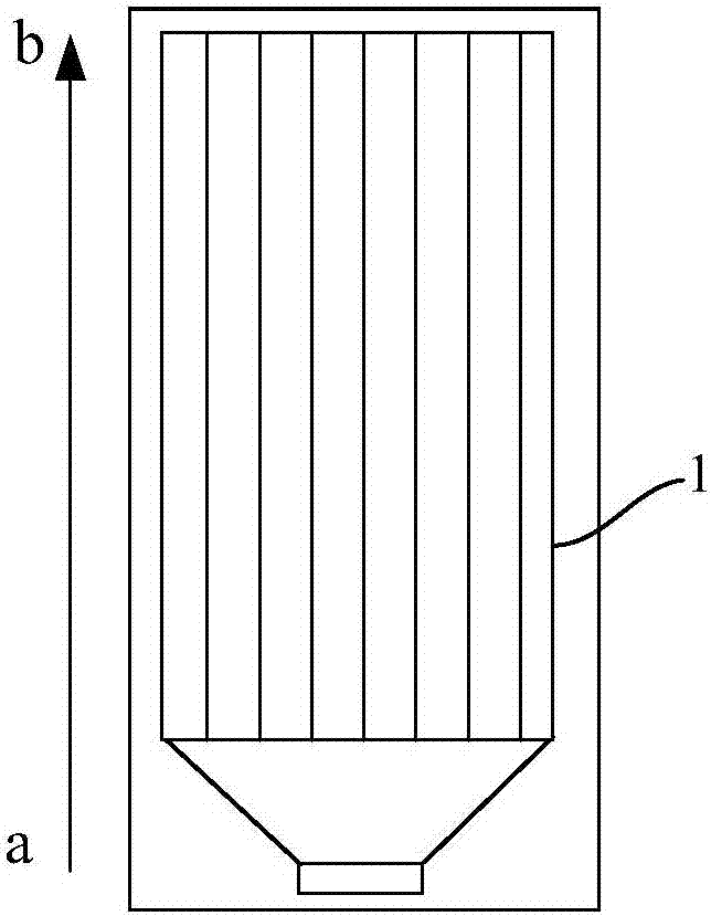
[0066] Such as image 3 The top view of the organ...


PUM


Abstract

The application relates to the technical field of the display, and in particular relates to an organic light-emitting display panel and a display device; the organic light-emitting display panel comprises a substrate and multiple pixel units arranged on the substrate; each pixel unit comprises a drain electrode, a pixel electrode and a light-emitting layer orderly arranged on the substrate; the organic light-emitting display panel further comprises multiple power signal transduction lines on the substrate; a conducting layer which comprises at least one first conducting part and multiple second conducting parts, wherein the first conducting part and the second conducting parts are insulated from each other, the multiple second conducting parts are insulated from each other, the first conducting part is electrically connected with multiple power signal transduction lines, and multiple second conducting parts are in one-to-one corresponding and electric connection with the drain electrode; a first insulating layer located between the conducting layer and the pixel electrode, wherein an electrode via hole is formed on the first insulating layer, and the pixel electrode is electrically connected with each second conducting part through the electrode via hole. The organic light-emitting display panel can enable the display brightness of the display device to be more uniform.

Description

technical field [0001] The present application relates to the field of display technology, in particular to an organic light emitting display panel and a display device. Background technique [0002] With the rapid development of the display field, the use of OLED display devices and liquid crystal display devices for display has become more popular in recent years. Therefore, people have put forward higher and higher requirements for the display performance of these display devices. [0003] The current routing of a display panel in traditional technology is as follows: figure 1 as shown, figure 1 One end of the power signal conducting line 1 in the power supply is connected to the current input end, and the other end extends to each pixel unit of the display device in turn, so as to provide driving current for each pixel unit. Specifically, the current input end of the display device is defined as end a, the other end is defined as end b, and the power signal conducting ...

Claims


Application Information

Patent Timeline
IPC IPC(8): H01L27/32
CPCH10K59/123H10K59/131H01L27/124G06F3/0412G06F3/0443H10K59/352H10K59/124H10K2102/3026G09G2310/0264G09G3/3225H10K50/805H10K59/40
Inventor 陈娴韩立静夏婉婉刘鹭
Owner WUHAN TIANMA MICRO ELECTRONICS CO LTD
Why Eureka
Try Eureka