
Anti-interference pneumatic finger and preparation method thereof

A pneumatic finger, anti-interference technology, applied in the directions of manipulators, manufacturing tools, chucks, etc., can solve the problems of inability to achieve different flexibility requirements, complex structure and control methods, poor practicability and stability, etc., to achieve simple structure and low production cost. , the effect of high work efficiency

Inactive Publication Date: 2017-09-22
CHANGZHOU COLLEGE OF INFORMATION TECH
View PDF6 Cites 2 Cited by
  • Summary
  • Abstract
  • Description
  • Claims
  • Application Information

AI Technical Summary

Problems solved by technology

[0003] The above-mentioned structure is very similar to the human finger, but there are still the following deficiencies in function in use: 1) The method of "metal phalanx + elastomer material" cannot meet the different flexibility requirements of surface contact when grasping different objects; 2) The use of " "Pneumatic + braided structure or elastomer material" is susceptible to external interference. When it collides with other objects or is impacted, it is easy to cause deformation and affect the accuracy of the action; 3) At present, most pneumatic fingers adopt a single-cavity structure with limited degrees of freedom. , it takes a certain amount of time to inflate and deflate. If multiple degrees of freedom are to be achieved, the structure and control methods are too complicated, and the practicability and stability are poor.

Method used


Image

  • Anti-interference pneumatic finger and preparation method thereof
  • Anti-interference pneumatic finger and preparation method thereof
  • Anti-interference pneumatic finger and preparation method thereof

Examples


Embodiment 1

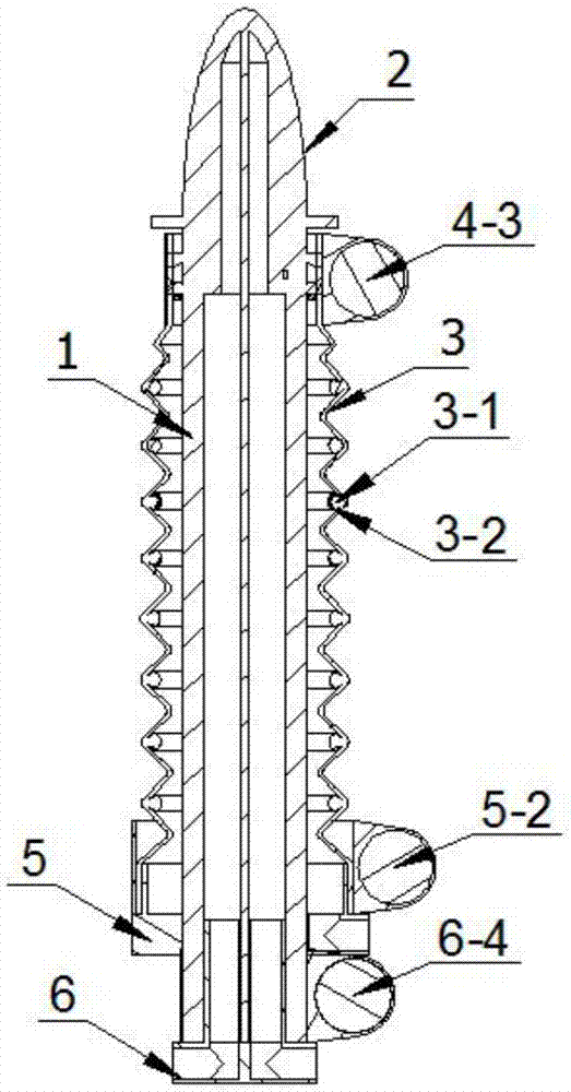
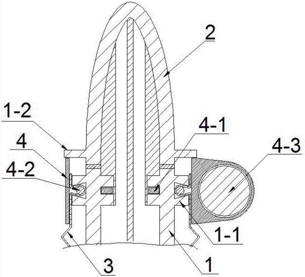
[0041] See Figure 1 to Figure 5 , The anti-interference pneumatic finger of this embodiment includes a pneumatic middle bone 1, an end finger 2, a wave-shaped cushioning jacket 3, an end coupling device 4, a bushing 5 and a root coupling 6.

[0042] The pneumatic middle bone 1 and the terminal fingers 2 are of an integrated structure. The pneumatic center bone 1 can adopt a variable cross-section structure as required, and the cross-section can be circular, rectangular or trapezoidal. Both the pneumatic center bone 1 and the end finger 2 are provided with two inner cavities, and the two inner cavities in the pneumatic center bone 1 communicate with the two inner cavities in the end finger 2 respectively.

[0043] The wave-shaped buffer jacket 3 is sheathed on the outside of the pneumatic centerbone 1, and a gap is provided between the inner surface of the wave-shaped buffer jacket 3 and the outer surface of the pneumatic centerbone 1. A wire ring 3-1 and a soft wire support...


PUM


Abstract

The invention discloses an anti-interference pneumatic finger and a preparation method thereof, wherein the wave-shaped buffer jacket of the anti-interference pneumatic finger is sleeved on the outside of the pneumatic center bone, and an inner surface of the wave-shaped buffer jacket and the outer surface of the pneumatic center bone are provided. There is a gap; the end of the wave-shaped buffer jacket is detachably sealed and fixedly connected with the end of the pneumatic center bone through the end coupling device; the bushing is detachably sealed and fixed between the proximal end of the pneumatic center bone and the proximal end of the wave-shaped buffer jacket , the bushing is provided with an outer inflation port that can inflate into the gap between the inner surface of the wave-shaped cushioning jacket and the outer surface of the aerodynamic bone; the finger root connector is detachably sealed and fixed on the proximal end of the pneumatic bone , There are two inner inflation ports that can respectively inflate air into the two inner cavities of the pneumatic centerbone on the finger joint. The invention has the advantages of anti-interference, high action precision, strong flexibility and low production cost, and has broad prospects.

Description

technical field [0001] The invention relates to an anti-interference pneumatic finger and a preparation method thereof. Background technique [0002] Soft robots are used in many fields, such as the grasping of fragile objects in the industrial field, the contact with human tissues in medical operations, the exploration and search and rescue in emergency rescue, the grasping and harvesting of fruits by agricultural robots, etc. . In order to achieve flexible grasping, the materials currently used include shape memory alloy (SMA), silica gel or rubber, and braided elastic fibers. The driving methods mainly include motor drive, mechanical cable drive (or cable drive), myoelectric control ( EMG), pneumatic etc. Taking the production of humanoid fingers as an example, the main structures include "metal phalanx + full elastic material (silicone or rubber)" (such as Chinese patent documents ZL200680048498.2, ZL201611177289.X), "Bowden wire + flexible exoskeleton" ( Such as Chin...

Claims


Application Information

Patent Timeline
IPC IPC(8): B25J15/08
CPCB25J15/08
Inventor 涂琴颜鹏陆修能
Owner CHANGZHOU COLLEGE OF INFORMATION TECH
Learn More