
Grounding resistance detection device

A grounding resistance and detection device technology, which is applied in the direction of grounding resistance measurement, signal transmission system, instrument, etc., can solve the problems that only the value of each point can be measured independently, and the grounding resistance measurement data cannot be transmitted remotely, so as to achieve the effect of easy installation and use

Inactive Publication Date: 2017-09-19
DANDONG ELECTRIC POWER SUPPLY COMPANY OF STATE GRID LIAONING ELECTRIC POWER SUPPLY +3
View PDF5 Cites 1 Cited by
  • Summary
  • Abstract
  • Description
  • Claims
  • Application Information

AI Technical Summary

Problems solved by technology

[0005] In view of the above problems, the present invention provides a grounding resistance detection device, which solves the problems that the grounding resistance measurement data cannot be transmitted remotely and can only measure the values ​​of each point independently.

Method used


Image

  • Grounding resistance detection device

Examples


Embodiment

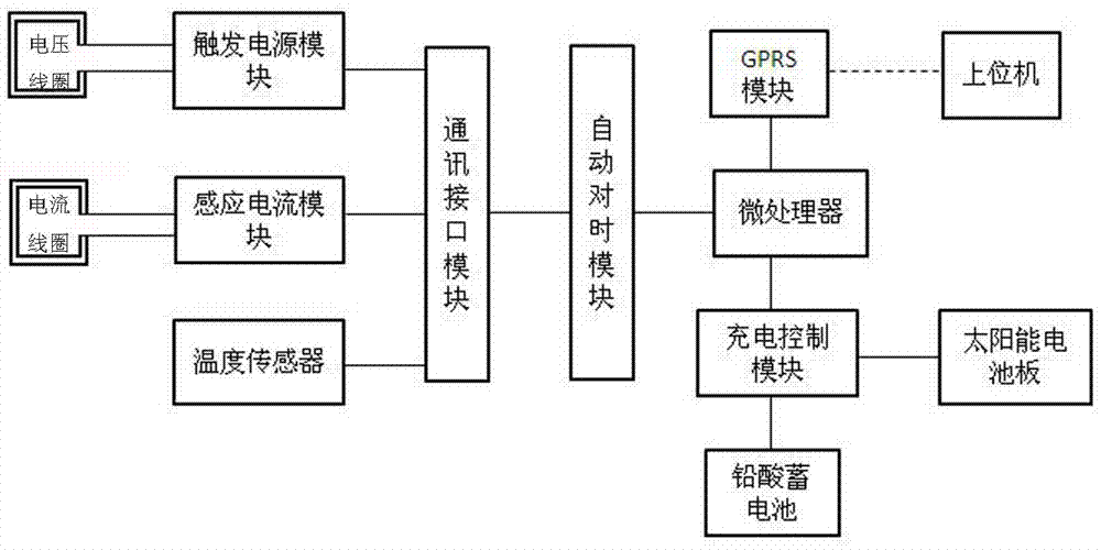
[0018] Such as figure 1 As shown, the ground resistance detection device includes a ground resistance sensor, a remote transmission device and a host computer. The ground resistance resistance sensor transmits the sensed current, voltage and temperature data to the remote transmission device through the communication interface, and the remote transmission device communicates with the host computer through GPRS. to communicate. The number of ground resistance sensors is at least one.

[0019] The ground resistance sensor includes a trigger power module, an induced current module and a temperature sensor. The trigger power module is connected to the voltage coil to provide an excitation signal and induce a potential E on the measured circuit. The induced current module is connected to the current coil. A current I is generated on the circuit, and the temperature sensor senses the temperature of the surrounding environment, triggering the power supply module, the induction curre...


PUM


Abstract

A grounding resistance detection device comprises a grounding resistance sensor, a remote transmission device and a host computer. The grounding resistance sensor transmits sensed current, voltage and temperature data to the remote transmission device through a communication interface. The remote transmission device communicates with the host computer through a GPRS. The beneficial effects are that a data transmission mode enabling an RS485 interface for transmission and 3G communication to be combined is employed for data transmission, so long-distance transmission of measured data information is realized; and in a calculation and analysis link, the host computer is adopted to calculate and analyze all-network grounding resistance in a concentrated manner, trend analysis is formed for all monitoring points, and data support is provided for timely discovering of fault hidden troubles.

Description

technical field [0001] The invention relates to a grounding resistance detection device, which belongs to the field of power system measurement. Background technique [0002] There are many grounding resistance testing methods currently used in China, including the potential drop method, two-point method, three-point method, three-pole method, four-pole method, high current method and clamp method. Among them, the potential drop method has been used since the 1960s. In this method, two auxiliary electrodes of voltage and current are arranged, and the potential drop curve of the grounding body and the voltage electrode is obtained by continuously changing the position of the voltmeter after measurement, and the measurement curve is analyzed to obtain the grounding resistance value. Although the potential drop method is recognized by researchers, it requires multiple measurements, a large workload, and the drawing of the potential drop curve is relatively difficult, which is ...

Claims


Application Information

Patent Timeline
IPC IPC(8): G01R27/20G08C17/02H02J7/35
CPCG01R27/20G08C17/02H02J7/35
Inventor 都兴凯于春光于鑫肖健韩利鹏于笑辰刘阳刘重远张广新赵立英
Owner DANDONG ELECTRIC POWER SUPPLY COMPANY OF STATE GRID LIAONING ELECTRIC POWER SUPPLY
Learn More