
A compressor stator blade with a large bending angle and a multi-section blade type connected in series at the root

A technology of stator blades and bending angles, which is applied in mechanical equipment, machines/engines, liquid fuel engines, etc., can solve problems such as difficult engineering implementation, no self-adaptability, and limited working condition range, and achieves reduced performance benefits and improved performance. The effect of engineering application prospects

Active Publication Date: 2019-07-02
BEIHANG UNIV
View PDF5 Cites 0 Cited by
  • Summary
  • Abstract
  • Description
  • Claims
  • Application Information

AI Technical Summary

Problems solved by technology

[0004] After decades of research, many scientific researchers have gained a deep understanding of the flow mechanism in the three-dimensional corner area of ​​the compressor. However, due to the complexity of its flow structure, as well as the limitations and reliability of experimental measurements and numerical simulations, At present, the accurate prediction and reliable control of the three-dimensional corner separation flow of the compressor have not been well realized according to the existing mechanical research results; the research on the three-dimensional corner separation flow mechanism, flow prediction and flow control of the compressor is always a high-performance Key Issues Concerned in Compressor Design
[0005] At present, the flow control technologies for the three-dimensional angular separation and stall of compressor stator blades can be divided into two categories: active control technology and passive control technology in terms of whether additional energy is introduced: active control technologies mainly include plasma excitation, boundary surface Layer blowing and suction technology, synthetic jet, etc.; passive control technology mainly includes vortex generators, wing blades, end wall molding, etc.; active control technology has a wide range of applications and obvious benefits, but it requires additional energy and is not easy to implement in engineering; the existing Traditional passive control technology is not self-adaptive, and the range of effective working conditions is often limited, which fails to solve the problem of corner separation of the next generation of high-load compressors in engineering

Method used


Image

  • A compressor stator blade with a large bending angle and a multi-section blade type connected in series at the root
  • A compressor stator blade with a large bending angle and a multi-section blade type connected in series at the root
  • A compressor stator blade with a large bending angle and a multi-section blade type connected in series at the root

Examples


Embodiment 1

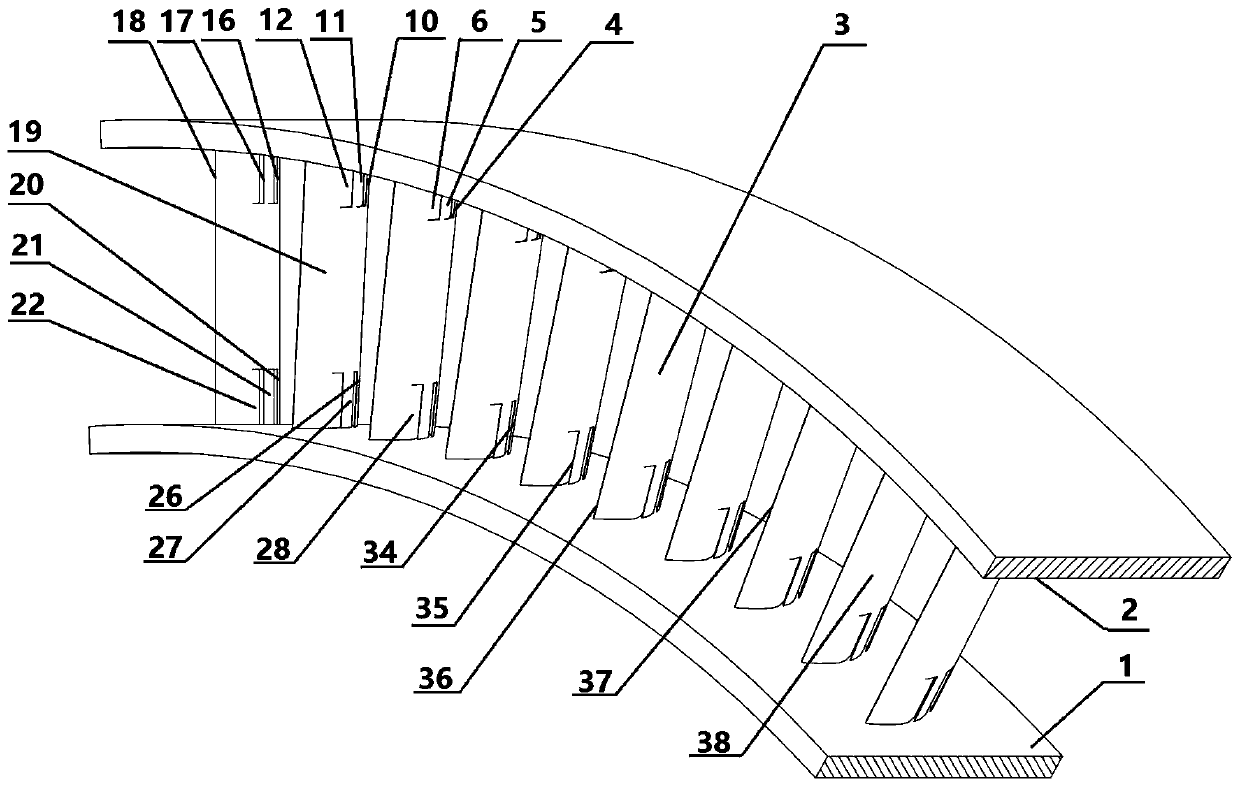
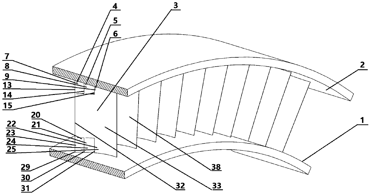
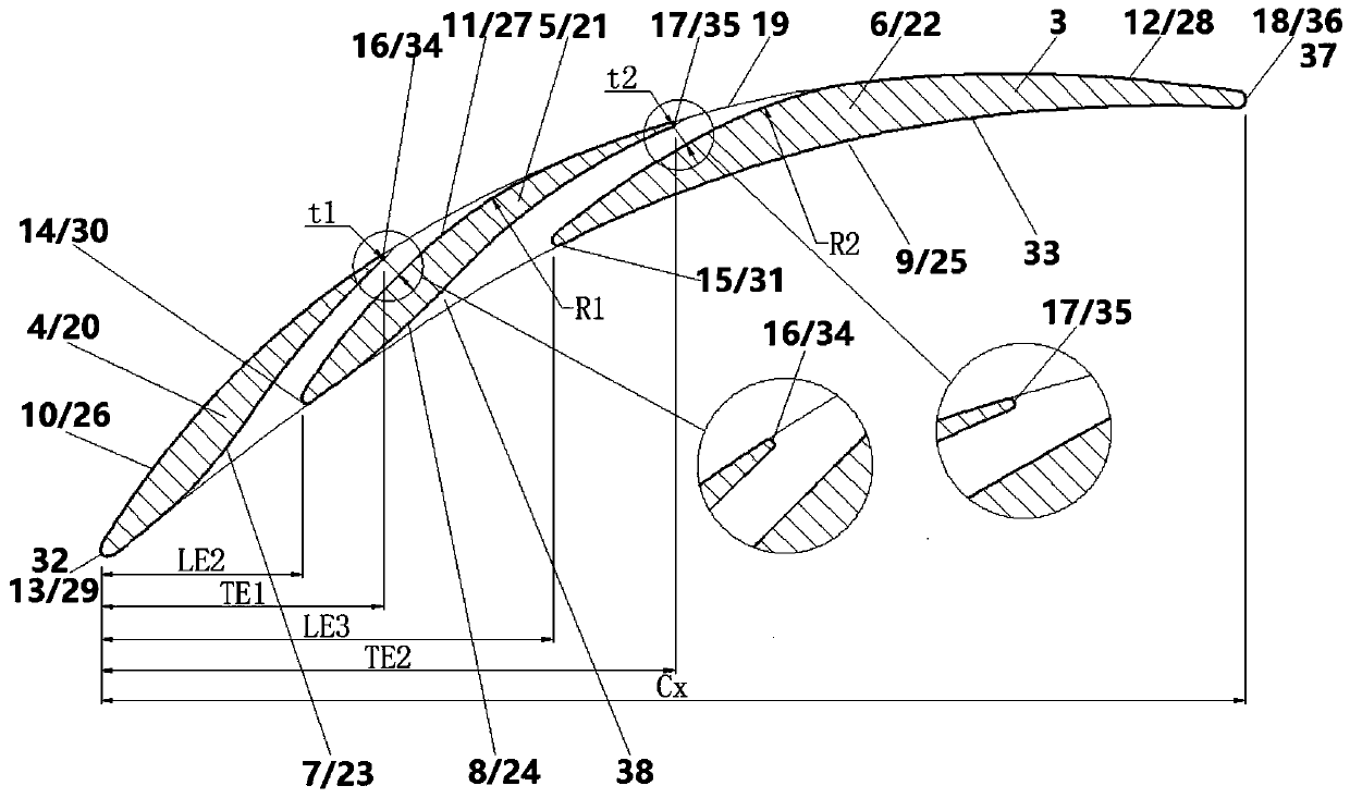
[0026] Such as figure 1 , figure 2 As shown, the large bending angle compressor stator blade of the present invention has a blade-shaped bending angle of 53 °, including the hub end wall 1, the casing end wall 2 and the stator blade 3, wherein the stator blade 3 is located between the casing end wall 2 and the hub Arranged in a circle between the end walls. The stator blade 3 is composed of the stator blade main body 38, small blades connected in series on the casing side one 4, two small blades connected in series on the casing side 21. Three small blades connected in series on the hub side are composed of three 22; small blades connected in series on the casing side one 4, small blades two connected in series on the casing side, three small blades connected in series on the casing side three 6 are used to connect the stator blade main body 38 and the casing end wall 2 , the airfoil section adopts continuous curvature airfoil design and has the same spanwise height, which ...

Embodiment 2

[0033] This embodiment is basically the same as Embodiment 1, the difference is that in this embodiment, the small blades connected in series on the casing side one 4 and the small blades connected in series on the hub side one 20 have different blade geometry, and the small blades connected in series on the casing side two 5 The second series small blade 21 on the hub side has a different airfoil geometry, the casing side series series small blade three 6 has a different blade geometry from the hub side series series small blade three 22, and the casing side series series small blades 4, 5, 6. The spanwise height is greater than the spanwise height of the small blades 20, 21, 22 connected in series on the hub side.


PUM


Abstract

The invention discloses a large bending angle air compressor stator blade serially connected with multiple sections of blade shapes at root part. The stator blade comprises hub end walls, chassis end walls and a stator blade, wherein the stator blade is formed by showing direction smooth connection of curvature continuous chassis side serial small blades with a stator blade body and the chassis end walls and showing direction smooth connection with curvature continuous hub side serial small blades with the stator blade body and the hub end walls; and the chassis side serial small blades and the hub side serial small blades have different blade shape geometries. Under the working conditions of different incoming currents, self-pressure-difference jet currents from gaps of serial small blades at the root part of the stator blade can be effectively acted on low-energy fluids in end areas of the stator blade, and carry the same to develop at the downstream to reconstruct end area flowing fields, so that the three-dimensional angular area separation / stall caused by accumulation of low-energy fluid groups in the end area of the stator blade under large bending angle is inhibited, the circulating capacity of a stator blade channel is improved, the effective working and working condition range of an air compressor stator is widened, and the performances under different working conditions are improved.

Description

technical field [0001] The invention relates to a compressor stator blade design scheme for suppressing separation of three-dimensional angular regions of a compressor stator blade, in particular to a compressor stator blade with a large bending angle whose roots are connected in series with multiple blade shapes, and belongs to the passive flow control technology in the technical field of turbomachinery. Background technique [0002] The compressor is the core component of the aviation gas turbine engine. It is composed of multi-stage rotors and stators arranged in a staggered order, and its function is to increase the gas pressure rise. [0003] In the flow inside the compressor, the secondary flow in the blade and end wall corner area caused by the large reverse pressure gradient is an inherent and complex flow phenomenon, so the loss is the main source of loss in the flow inside the compressor; three-dimensional The flow congestion caused by corner separation / stall makes...

Claims


Application Information

Patent Timeline
Patent Type & Authority Patents(China)
IPC IPC(8): F04D29/54F04D29/66
CPCF04D29/542F04D29/544F04D29/667F05D2240/121F05D2240/123F05D2240/124F05D2240/126
Inventor 唐雨萌柳阳威陆利蓬王鸣
Owner BEIHANG UNIV
Learn More