AB glue mixing device

A technology of mixing device and glue rod, applied in the field of AB glue mixing device, can solve the problems of inability to accurately control the running distance of the first cylinder and the second cylinder, inability to accurately control the mixing ratio of A glue and B glue, and inability to obtain AB glue, etc.

Pending Publication Date: 2017-09-12
SEKSUN TECH SUZHOU
View PDF5 Cites 0 Cited by
  • Summary
  • Abstract
  • Description
  • Claims
  • Application Information

AI Technical Summary

Problems solved by technology

[0002] In the current AB glue mixing device, the AB glue mixing device includes A glue storage, B glue storage, AB glue mixer, first cylinder, second cylinder and proportional valve; wherein, A glue storage There is a first glue push rod inside and a second glue push rod inside the B glue storage container; through the first cylinder to push the first glue push rod and the second cylinder to push the second glue push rod, A glue and B glue are placed in the The AB glue is mixed in the mixer, and the speed or pressure control of the first cylinder and the second cylinder is realized through the proportional valve; because the first cylinder and the second cylinder use the proportional valve to realize simple speed or pressure control, so that the first cylinder And the second cylinder does not have the precise positioning function of start and stop, and the running distance of the first cylinder and the second cylinder cannot be precisely controlled, that is, the mixing ratio of A glue and B glue cannot be precisely controlled, resulting in the inability to obtain the required AB glue

Method used


Image

  • AB glue mixing device
  • AB glue mixing device

Examples


Embodiment approach

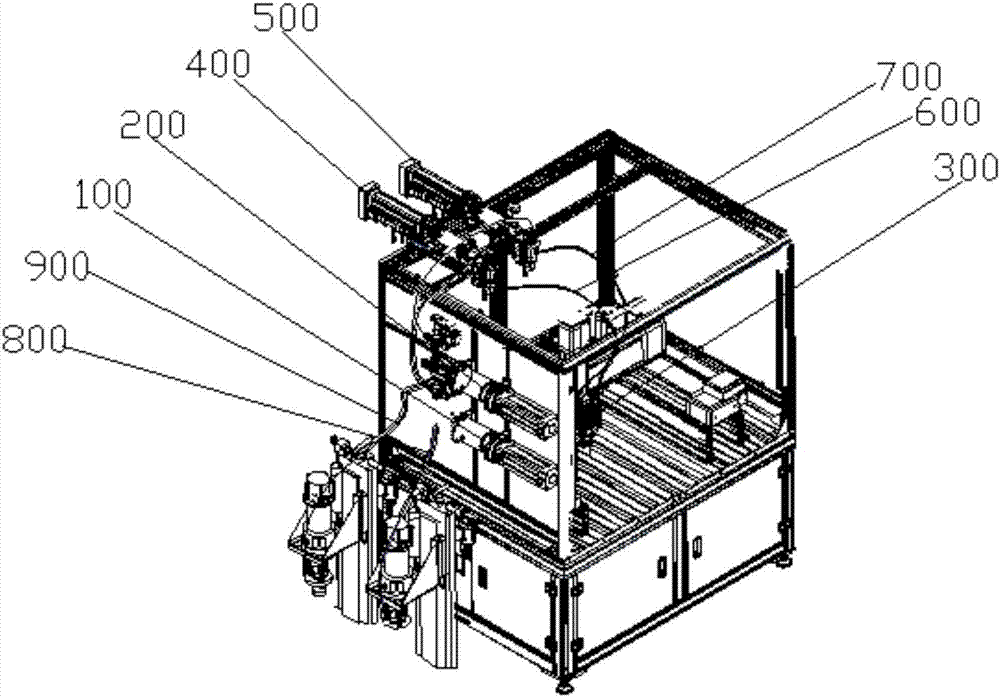
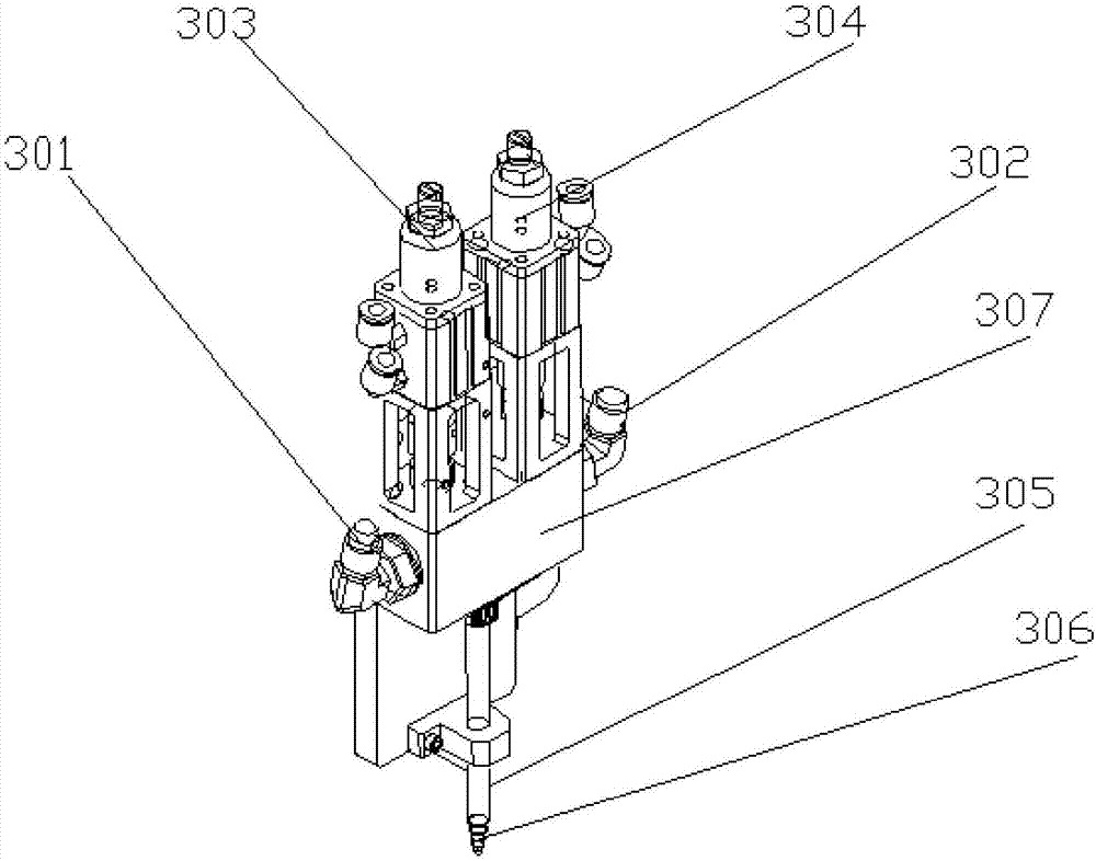
[0048] According to an embodiment of the AB glue mixing device of the present invention, the AB glue mixing device also includes a first ball valve, a second ball valve, a first glue outlet pipe 600 and a second glue outlet pipe 700; the AB glue mixer 300 includes an A glue inlet Port 301 and B glue inlet port 302; wherein, the first ball valve includes a first glue outlet; the second ball valve includes a second glue outlet;

[0049] The first glue outlet communicates with the A glue storage device 100 and is electrically connected to the controller; the second glue outlet communicates with the B glue storage device 200 and is electrically connected to the controller;

[0050] The first glue outlet communicates with the A glue inlet 301 through the first glue outlet tube 600 ; the second glue outlet communicates with the B glue inlet 302 through the second glue outlet tube 700 .

[0051] According to an embodiment of the AB glue mixing device of the present invention, the fir...


PUM


Abstract

The invention discloses an AB glue mixing device, and relates to the technical field of glue mixing pipes. The AB glue mixing device comprises an A glue storage appliance, a B glue storage appliance, an AB glue mixing appliance, a first electric cylinder, a second electric cylinder and a controller, wherein the A glue storage appliance is used for holding A glue; the B glue storage appliance is used for holding B glue; the AB glue mixing appliance is used for mixing the A glue with the B glue to form AB glue; the first electric cylinder is used for pushing the A glue to the AB glue mixing appliance; the first electric cylinder is connected with the A glue storage appliance; the second electric cylinder is used for pushing the B glue to the AB glue mixing appliance; the second electric cylinder is connected with the B glue storage appliance; the controller is electrically connected with the first electric cylinder and the second electric cylinder respectively. According to the AB glue mixing device provided by the invention, the AB glue mixing device can accurately control the mixing proportion of the A glue to the B glue; the required AB glue is formed.

Description

technical field [0001] The invention relates to the technical field of mixing rubber hoses, in particular to an AB glue mixing device. Background technique [0002] In the current AB glue mixing device, the AB glue mixing device includes A glue storage, B glue storage, AB glue mixer, first cylinder, second cylinder and proportional valve; wherein, A glue storage There is a first glue push rod inside and a second glue push rod inside the B glue storage container; through the first cylinder to push the first glue push rod and the second cylinder to push the second glue push rod, A glue and B glue are placed in the The AB glue is mixed in the mixer, and the speed or pressure control of the first cylinder and the second cylinder is realized through the proportional valve; because the first cylinder and the second cylinder use the proportional valve to realize simple speed or pressure control, so that the first cylinder And the second cylinder does not have the precise positioni...

Claims


Application Information

Patent Timeline
Patent Type & Authority Applications(China)
IPC IPC(8): B01F3/08B01F15/00
CPCB01F23/40B01F35/20B01F2101/36
Inventor 袁斐耿振强朱志球
Owner SEKSUN TECH SUZHOU
Why Eureka
Try Eureka