
Intelligent commutation control device and commutation control method

A control device and phase control technology, applied in the field of distribution network, can solve problems such as unacceptable power supply department and users, current increase, power supply interruption, etc., and achieve short-term and reliable switching operation

Active Publication Date: 2017-09-08
BINZHOU POWER SUPPLY COMPANY OF STATE GRID SHANDONG ELECTRIC POWER +1
View PDF4 Cites 1 Cited by
  • Summary
  • Abstract
  • Description
  • Claims
  • Application Information

AI Technical Summary

Problems solved by technology

The unbalanced three-phase load causes an increase in the loss of distribution transformers and load lines in the distribution station area, a decrease in the voltage quality of the heavy-load phase in the distribution station area, a decrease in the output of the distribution transformer, and a decrease in the power conversion efficiency. The zero-sequence current of the electric transformer increases, and the eddy current loss caused by it increases the operating temperature of the distribution transformer, endangering the safety and life of the transformer.
But the disadvantage is that the conventional reversing switch is based on the mechanical opening and closing operation, and there is a short-term power interruption during the switching period, which cannot be accepted by the power supply department and users

Method used


Image

  • Intelligent commutation control device and commutation control method
  • Intelligent commutation control device and commutation control method
  • Intelligent commutation control device and commutation control method

Examples


Embodiment Construction

[0046] In order to make the purpose, features and advantages of the present invention more obvious and understandable, the technical solutions protected by the present invention will be clearly and completely described below using specific embodiments and accompanying drawings. Obviously, the implementation described below Examples are only some embodiments of the present invention, but not all embodiments. Based on the embodiments in this patent, all other embodiments obtained by persons of ordinary skill in the art without creative efforts fall within the protection scope of this patent.

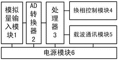
[0047] This embodiment provides an intelligent commutation control device, such as figure 1 As shown, it includes: an analog input module 1, an AD converter 2, a processor 3, a commutation control module 4, a carrier communication module 5 and a power supply module 6 for providing power to internal components of the intelligent commutation control device;

[0048] The analog input module ...


PUM


Abstract

The invention provides an intelligent commutation control device and a commutation control method. A processor is used for receiving a three-phase voltage signal and a three-phase current signal, transmitted by an analog input model, of a power distribution network, and the three-phase voltage, load current amplitude and a phase are calculated by a half-wave Fourier transformation algorithm to achieve functions of measurement displaying, communication and remote transmission; after a commutation instruction emitted from an area control terminal is received, a voltage sampling waveform and a current sampling waveform are judged in real time, and a commutation control module is controlled to emit the commutation instruction to achieve commutation action; after the commutation action is completed, an operation result is uploaded to the area control terminal by a carrier communication module; and the commutation control module is used for controlling an electronic commutation switch to execute phase action according to the commutation instruction emitted by the process. By the intelligent commutation control device and the commutation control method, a intelligent seamless commutation technology is achieved, a voltage phase zero-cross point and a current phase zero-cross point are traced in real time during the whole processes of commutation instruction receiving and commutation completion, the switching operation consumes short time and is reliable, and moreover, no commutation overlap is ensured.

Description

technical field [0001] The invention relates to the field of distribution networks, in particular to an intelligent commutation control device and a commutation control method. Background technique [0002] There are many power users in my country's distribution network and their locations are scattered, and there are a large number of single-phase loads with unbalanced spatio-temporal distribution, resulting in varying degrees of unbalanced three-phase loads in most distribution areas. The unbalanced three-phase load will increase the loss of distribution transformers and load lines in the distribution station area, the voltage quality of the heavy-load phase in the distribution station area will decrease, the output of the distribution transformer will decrease, and the power conversion efficiency will decrease. The eddy current loss caused by the increase of the zero-sequence current of the electric transformer increases the operating temperature of the distribution trans...

Claims


Application Information

Patent Timeline
Patent Type & Authority Applications(China)
IPC IPC(8): H02J3/26
CPCH02J3/26Y02E40/50
Inventor 丁锐刘海泳王官涛王晖伊瑞鹏代佰华庞波李平郭增民李巍朱洪防张力高涛高峰王忠友吴晓东
Owner BINZHOU POWER SUPPLY COMPANY OF STATE GRID SHANDONG ELECTRIC POWER
Learn More