Eureka AIR delivers breakthrough ideas for toughest innovation challenges, trusted by R&D personnel around the world.

Long-distance mass-batch wire laying device at region

A large-scale, long-distance technology, applied in cable laying equipment, transportation and packaging, transportation of filamentous materials, etc., can solve the problems of high production cost and lack of universality, reduce mechanical damage, improve labor efficiency, The effect of reducing the labor intensity of workers

Pending Publication Date: 2017-09-08
上海山安建设工程有限公司
View PDF12 Cites 2 Cited by
  • Summary
  • Abstract
  • Description
  • Claims
  • Application Information

AI Technical Summary

Problems solved by technology

Although fully automatic, high-speed, precise and continuous wiring can be realized, the production cost is relatively high
And it needs a specific working environment, not universal

Method used


Image

  • Long-distance mass-batch wire laying device at region
  • Long-distance mass-batch wire laying device at region

Examples


Embodiment Construction

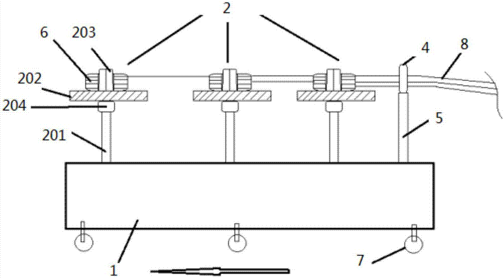
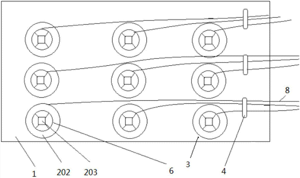
[0016] see figure 1 with figure 2 , the long-distance and large-volume wire laying device in intervals includes: a rack plate 1, a pay-off mechanism array composed of a pay-off mechanism 2 and a closing coil 4; the pay-off mechanism array is arranged vertically and horizontally on the frame The top of the disc 1; the closing coil 4 is fixed on the frame disc 1 through the connecting rod 5, and is located at the edge of each line pay-off mechanism 2; the described pay-off mechanism includes a support column 201, a wire reel tray 202 and a rotating shaft 203; the bottom of the support column 201 is fixed on the frame disc 1, and the wire tray tray 202 is connected with the upper end of the support column 201 through a rotating member 204 such as a bearing; The outer surface of the rotating shaft 203 is provided with a reel positioning mechanism that cooperates with the outer surface of the reel 6, and the lower end of the rotating shaft 203 is fixed on the upper surface of the...


PUM


Abstract

The invention discloses a long-distance mass-batch wire laying device at a region. The long-distance mass-batch wire laying device comprises a machine frame carrier, a wire uncoiling mechanism array formed by wire uncoiling mechanisms, and compound coils, wherein the wire uncoiling mechanism array is arrayed on the machine frame carrier vertically and horizontally; the compound coils are separately fixed to the machine frame carrier through a connecting rod, and located at the edge of each line of wire uncoiling mechanisms; each wire uncoiling mechanism comprises a supporting column, a wire carrier tray and a rotating shaft; the bottom of each supporting column is fixed to the machine frame carrier; each wire carrier tray is connected with the corresponding supporting column through a corresponding rotating member; a wire carrier positioning mechanism matched with the outer surface of each wire carrier is arranged on the outer surface of each rotating shaft; and the lower end of each rotating shaft is fixed to the corresponding wire carrier tray. According to the long-distance mass-batch wire laying device disclosed by the invention, the construction cost can be effectively reduced, the construction progress is accelerated, the labor intensity is reduced, the disassembling and the assembling are convenient, the moving is convenient, the mechanical damage of wires in the process of wire uncoiling of conducting wires is reduced, and the construction quality is improved.

Description

technical field [0001] The present invention relates to wire laying mechanisms. Background technique [0002] Wire laying through pipes is a frequently encountered project in the construction industry. It usually requires a large number of multi-channel multi-phase wires to be laid over long distances in the interval. However, in the conventional practice, the setting-out process is labor intensive and the construction speed is relatively slow. [0003] In order to overcome the above-mentioned defects, CN102868126A discloses a wire wiring device whose structure is too complicated to be popularized and applied. [0004] CN102897593A discloses a cable arrangement control system and method, including a servo motor, a lead screw, a cable arrangement mechanism, an I-shaped wheel, a first encoder and a motion controller; wherein, the servo motor, the lead screw and the The wire arranging mechanism is connected; the first encoder is arranged on the I-shaped wheel; the motion cont...

Claims


Application Information

Patent Timeline
Patent Type & Authority Applications(China)
IPC IPC(8): B65H49/30B65H57/06H02G1/08
CPCH02G1/08B65H49/30B65H57/06B65H2701/34
Inventor 李新龙吕荣军王利民霍雨佳冯玉保
Owner 上海山安建设工程有限公司
Why Eureka
Eureka Blog
Learn More