Wiper for rearview mirror
A rearview mirror and wiper technology, which is applied in vehicle cleaning, vehicle maintenance, optical observation devices, etc., can solve problems that affect the observation of the vehicle, blur the viewing effect, and affect driving safety, so as to improve driving safety and improve visual clarity degree of effect
- Summary
- Abstract
- Description
- Claims
- Application Information
AI Technical Summary
Problems solved by technology
Method used
Image
Examples
Embodiment 1
[0033] This embodiment is an illustration of installing the wiper on the rearview mirror, and the wiper installed on the rearview mirror does not affect the original direction adjustment function of the rearview mirror.
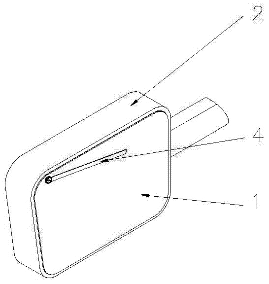
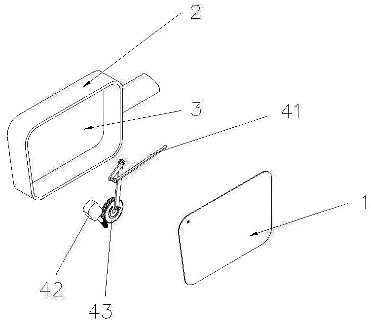
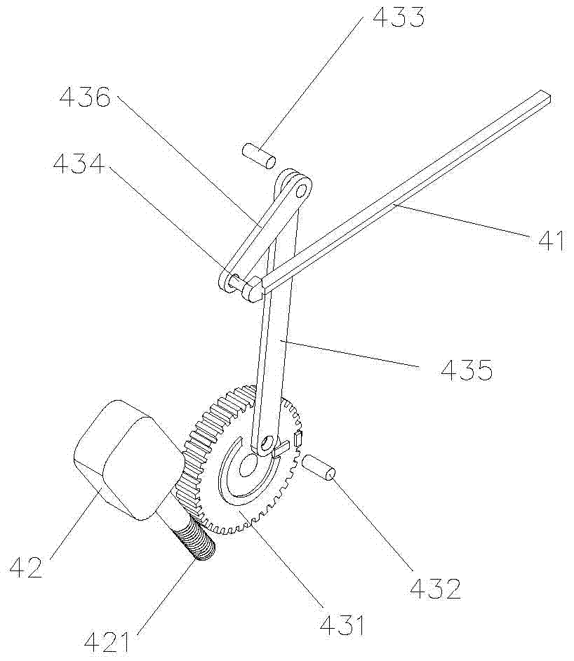
[0034] see figure 1 , figure 2 and image 3 , a wiper for a rearview mirror according to the present invention, comprising a mirror 1, a frame 2 for installing the mirror 1, an accommodating space 3 between the mirror 1 and the frame 2, and a wiper assembly 4, the wiper The assembly 4 includes a rearview mirror wiper blade 41 for scraping the mirror surface 1, a drive source 42 connected to the mirror frame 2, a drive connected to the drive source 42 and used to control the swing of the rearview mirror wiper blade 41. device 43;
[0035] Both the driving source 42 and the transmission device 43 are disposed in the accommodating space 3 .
[0036] The output end of the driving source 42 is provided with a worm 421, and the transmission device 43 is provid...
Embodiment 2
[0049] In this embodiment, the wiper is installed on the side door glass.
[0050] Please refer to Figure 5 to Figure 8Specifically, in this implementation, the driving source 42 and the transmission device 43 in the wiper assembly 4 are installed in the inner cavity of the box body 8, and the box body 8 is screwed to the outside of the vehicle side door 7. The side door wiper piece 44 is connected to the side of the glass window 6 near the rearview mirror. The first connecting rod 435 in the transmission device 43 protrudes from the outside of the box body 8 through the through hole 81 on the upper end surface of the box body 8. The driving source 42 adopts a DC12V motor, the output end of the motor is equipped with a worm 421, and a transmission gear 431 meshed with the worm 421, the worm 421 rotates and drives the transmission gear 431 to rotate, and the eccentric shaft 432 installed on the end face of the transmission gear 431 rotates synchronously with the transmission g...
PUM
 Abstract
Description
Claims
Application Information
 - Generate Ideas
- Intellectual Property
- Life Sciences
- Materials
- Tech Scout
- Unparalleled Data Quality
- Higher Quality Content
- 60% Fewer Hallucinations
Browse by: Latest US Patents, China's latest patents, Technical Efficacy Thesaurus, Application Domain, Technology Topic, Popular Technical Reports.
© 2025 PatSnap. All rights reserved.Legal|Privacy policy|Modern Slavery Act Transparency Statement|Sitemap|About US| Contact US: help@patsnap.com


