
Surface crack identification method based on fused time frequency characteristics

A recognition method and technology of time-frequency characteristics, which are applied in image data processing, instruments, calculations, etc., to achieve the effect of suppressing noise, small interference, and accurate crack location.

Inactive Publication Date: 2017-09-05
ZHEJIANG UNIV OF TECH
View PDF2 Cites 5 Cited by
  • Summary
  • Abstract
  • Description
  • Claims
  • Application Information

AI Technical Summary

Problems solved by technology

[0004] In order to solve the various limitations of manual inspection, it is necessary to use advanced surface defect detection methods to detect surface defects of products

Method used


Image

  • Surface crack identification method based on fused time frequency characteristics
  • Surface crack identification method based on fused time frequency characteristics
  • Surface crack identification method based on fused time frequency characteristics

Examples


Embodiment Construction

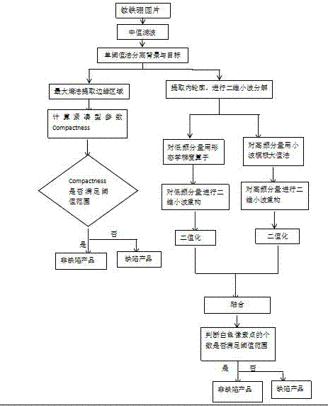
[0024] A method for identifying cracks on the surface of NdFeB discs with time-frequency features, comprising the following steps:

[0025] Step 1: Obtain real-time images of NdFeB wafers on the assembly line through visual equipment;

[0026] Step 2: Carry out median filter preprocessing on the image to eliminate noise. Specific steps are as follows:

[0027] 2.1 Move the 3*3 filter template in the image, and make the center of the filter template coincide with a certain pixel position of the image;

[0028] 2.2 Read the gray value of each corresponding pixel in the template;

[0029] 2.3 Arrange these gray values ​​in ascending order;

[0030] 2.4 The output of two-dimensional median filtering is g(x,y)=med{f(x-k,y-l),(k,l∈W)}, where f(x,y) and g(x,y) are respectively Original image pixels and processed image pixels. W is a two-dimensional template, which is a 3*3 area.

[0031] Step 3, use the single threshold segmentation method to separate the background and the tar...


PUM


Abstract

The invention discloses a surface crack identification method based on fused time frequency characteristics. A real-time image of a neodymium iron boron wafer on a production line is obtained by a visual device; noise elimination, background and target separation are carried out on the image; the area of a target region is calculated; the edge region of the target image is extracted, and the circumference of a boundary is calculated; compact-type parameters are calculated; a region in an outer contour is extracted as a region of interest, the outer contour is eliminated, and wavelet decomposition is carried out on the image; local analysis is carried out on the image; obtained low-frequency and high-frequency defect edge images are subjected to binarization processing; and a final crack image is obtained for crack identification. The method has the advantages of effectively suppressing noise and being good in robustness.

Description

technical field [0001] The invention relates to the field of computer vision detection, in particular to a method for identifying chipped edges and cracks on the surface of an NdFeB wafer. Background technique [0002] Magnetic material devices are widely used in various fields such as instruments and motors. NdFeB permanent magnet materials are a very important material in the development of low-carbon industries. NdFeB has extremely high magnetic energy product and coercive force, and the advantages of high energy density make NdFeB permanent magnet materials widely used in modern industry and electronic technology. Various defects caused by the magnetic sheet during processing seriously affect its quality, and the magnetic sheet needs to pass strict quality tests before it becomes a product. Traditionally, human eyes are generally used to judge, that is, manual visual inspection, and various measuring tools are used to measure. The detection effect is greatly affected by...

Claims


Application Information

Patent Timeline
Patent Type & Authority Applications(China)
IPC IPC(8): G06T7/00G06T7/13G06T7/136G06T7/149G06T7/194G06T7/62
CPCG06T7/0004G06T7/13G06T7/136G06T7/149G06T7/194G06T7/62G06T2207/20221G06T2207/30108
Inventor 姚明海袁慧顾勤龙王宪保
Owner ZHEJIANG UNIV OF TECH
Learn More