Garbage press-drying incineration device

An incineration device and garbage technology, applied in the direction of incinerators, combustion methods, combustion types, etc., can solve the problems of inconvenient replacement of electric heating tubes, burning of moisture in garbage, etc., and achieve the effect of easy operation and simple replacement steps

Active Publication Date: 2017-09-05
佛山标天下信息科技有限公司
View PDF6 Cites 1 Cited by
  • Summary
  • Abstract
  • Description
  • Claims
  • Application Information

AI Technical Summary

Problems solved by technology

[0002] With the continuous development of society and the continuous improvement of urbanization construction, more and more people are pouring into the city, making the population density of the city become larger and larger, and the domestic waste is gradually increasing with the continuous increase of the population. These domestic wastes have affected people's production and life. How to deal with these domestic wastes has become a top priority for people now. Among them, incineration of waste is an effective way to deal with it. The incineration of waste is completed by incinerators. Combustion of coal, fuel oil, gas and other fuels, the objects to be processed are incinerated and carbonized at high temperature to achieve the purpose of disinfection, but domestic waste has a lot of water before incineration, making it difficult for the incinerator to burn the waste containing water , in order to remove the moisture in the domestic waste before incineration in the incinerator, a waste pressing and drying incineration device has appeared on the market. The existing waste pressing and drying incineration device also uses a drying device to dry the squeezed domestic waste. Due to the drying The drying device is directly welded on the frame of the garbage pressing and drying incineration device, so it is not convenient to replace the electric heating tube inside the drying device

Method used


Image

  • Garbage press-drying incineration device
  • Garbage press-drying incineration device
  • Garbage press-drying incineration device

Examples


Embodiment

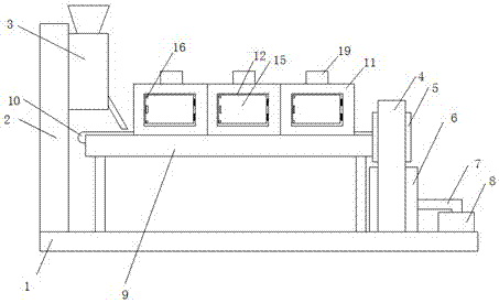
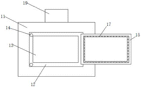
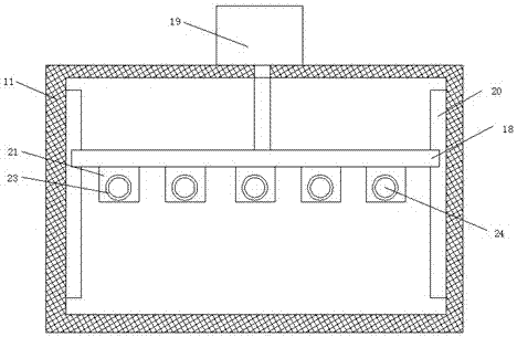
[0023] refer to Figure 1-4 , the present embodiment proposes a rubbish dry incineration device, including a rectangular placement seat 1, a mounting vertical plate 2 installed on one side of the top of the placement seat 1, and a U-shaped installation frame 4 installed on both sides of the top of the placement seat 1, Garbage extruding equipment 3 is installed on the top of the installation vertical plate 2 near the U-shaped mounting frame 4. The inboard of the U-shaped mounting frame 4 is equipped with a cutting device 5, and the bottom of the cutting device 5 is provided with an incineration device installed on the top of the placement seat 1. The furnace 6 is provided with a frame 9 installed on the top of the placement seat 1 between the vertical plate 2 and the U-shaped mounting frame 4, and the top of the frame 9 is welded with three drying boxes 11 arranged in sequence from left to right, The bottom of the drying box 11 is provided with an opening, and one side of the ...


PUM


Abstract

The invention discloses a garbage press-drying incineration device. The garbage press-drying incineration device comprises a rectangular containing seat, a mounting vertical plate mounted on one side of the top of the containing seat and a U-type mounting rack mounted on the two sides of the top of the containing seat. Garbage extrusion equipment is mounted at the top of the side, close to the U-type mounting rack, of the mounting vertical plate. Cutting equipment is mounted on the inner side of the U-type mounting rack, and an incinerator mounted at the top of the containing seat is arranged below the cutting equipment. A rack mounted at the top of the containing seat is arranged between the mounting vertical plate and the U-type mounting rack, and three drying box bodies arranged in sequence from left to right are welded to the top of the rack. An opening is formed in the bottom of each drying box body, and a first rectangular groove is formed in one side of each drying box body. A second rectangular groove is formed in the inner wall of the side, close to the interior of the corresponding drying box body, of each first rectangular groove. The garbage press-drying incineration device is economical and practical, electric heating pipes in the drying box bodies can be conveniently replaced by workers, the replacement step of the electric heating pipes is simple, and the workers can achieve operation easily.

Description

technical field [0001] The invention relates to the technical field of garbage treatment equipment, in particular to a garbage pressing and incineration device. Background technique [0002] With the continuous development of society and the continuous improvement of urbanization construction, more and more people are pouring into the city, making the population density of the city become larger and larger, and the domestic waste is gradually increasing with the continuous increase of the population. These domestic wastes have affected people's production and life. How to deal with these domestic wastes has become a top priority for people now. Among them, incineration of waste is an effective way to deal with it. The incineration of waste is completed by incinerators. Combustion of coal, fuel oil, gas and other fuels, the objects to be processed are incinerated and carbonized at high temperature to achieve the purpose of disinfection, but domestic waste has a lot of water b...

Claims


Application Information

Patent Timeline
Patent Type & Authority Applications(China)
IPC IPC(8): F23G5/10F23G5/033F23G5/44
CPCF23G5/033F23G5/10F23G5/444
Inventor 周鸣晨
Owner 佛山标天下信息科技有限公司
Why Eureka
Try Eureka