
A Parallel Mechanism with Few Joints and Two Rotation Degrees of Freedom

A technology of degrees of freedom and joints, applied in the field of robotics, can solve problems such as low overall stiffness, difficult processing and manufacturing, and incomplete decoupling of mechanisms, and achieve the effect of simple control model, high structural rigidity, and strong practicability

Active Publication Date: 2020-02-04
YANSHAN UNIV
View PDF2 Cites 0 Cited by
  • Summary
  • Abstract
  • Description
  • Claims
  • Application Information

AI Technical Summary

Problems solved by technology

The two-degree-of-freedom rotating parallel mechanism includes a two-degree-of-freedom spherical mechanism and a two-degree-of-freedom rotating parallel mechanism without a meeting point. The two rotational axes of the two-degree-of-freedom spherical parallel mechanism are continuous, but it must satisfy that the axis of the rotating pair meets at a certain point. It is very difficult to process and manufacture due to the geometrical requirements of points; however, there are not many existing two-degree-of-freedom parallel mechanisms without converging points that have two continuous shafts, and the number of single-degree-of-freedom kinematic pairs is large, and the overall stiffness is low, such as The institutions proposed in Chinese patent CN201010136427.6, etc.
The mechanism proposed by CN201610303875.8 has two continuous shafts, but the mechanism is not completely decoupled
The above two-rotation parallel mechanisms with two continuous shafts also have problems such as a large number of single-degree-of-freedom joints.

Method used


Image

  • A Parallel Mechanism with Few Joints and Two Rotation Degrees of Freedom
  • A Parallel Mechanism with Few Joints and Two Rotation Degrees of Freedom
  • A Parallel Mechanism with Few Joints and Two Rotation Degrees of Freedom

Examples


Embodiment 1

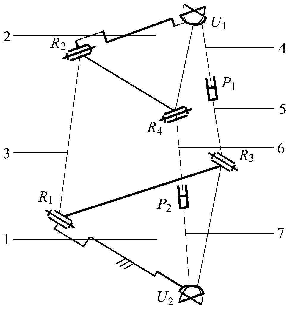
[0016] exist figure 1 In the schematic diagram of the two-rotation parallel mechanism with few joints shown, one end of the intermediate link 3 of the first branch chain is connected to the moving platform 2 through the rotating pair R2, and the other end of the intermediate connecting rod is connected to the fixed platform 1 through the rotating pair R1; One end of the first upper link 4 of the branch chain is connected to the moving platform through the Hooke hinge U1, the other end of the first upper link is connected to one end of the first lower link 5 through the moving pair P1, and the other end of the first lower link is It is connected with the fixed platform through the rotating pair R3; one end of the second upper link 6 of the third branch chain is connected with the moving platform through the rotating pair R4, and the other end of the second upper link is connected with the second lower link 7 through the moving pair P2. The other end of the second lower link is ...

Embodiment 2

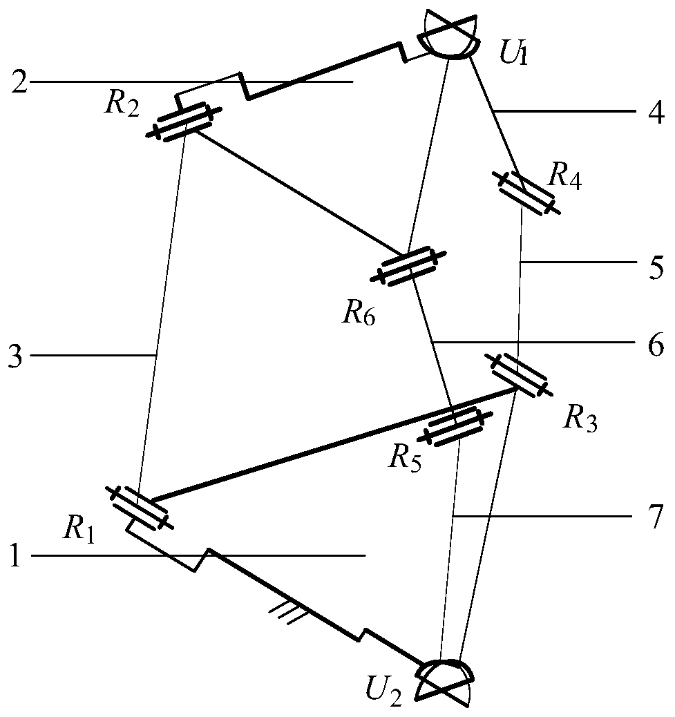
[0018] Such as figure 2 As shown, one end of the middle connecting rod 3 of the first branch chain is connected to the moving platform 2 through the rotating pair R2, and the other end of the middle connecting rod is connected to the fixed platform 1 through the rotating pair R1; the first upper connecting rod 4 of the second branch chain One end is connected to the moving platform through the Hooke hinge U1, the other end of the first upper link is connected to one end of the first lower link 5 through the rotation pair R6, and the other end of the first lower link is connected to the fixed platform through the rotation pair R3; One end of the second upper link 6 of the third branch chain is connected with the moving platform through the rotation pair R4, and the other end of the second upper link is connected with the second lower link 7 through the rotation pair R5. One end is connected to the fixed platform through the Hooke hinge U2. The axes of revolving pair R2 and re...

Embodiment 3

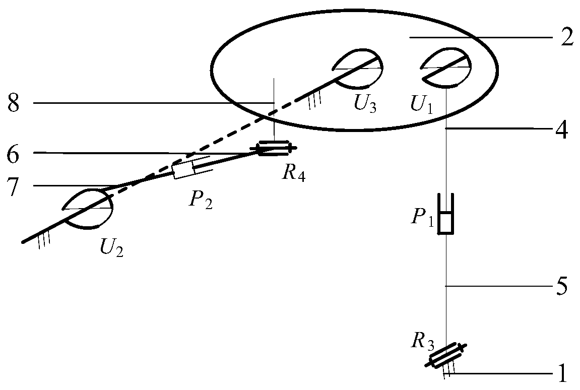
[0020] Such as image 3 As shown, the first branch chain connects the fixed platform 1 and the moving platform 2 through the Hooke hinge U3; one end of the first upper link 4 of the second branch chain is connected with the moving platform through the Hooke hinge U1, and the first upper link The other end is connected to one end of the first lower connecting rod 5 through the moving pair P1, and the other end of the first lower connecting rod is connected to the fixed platform through the rotating pair R3; the second upper connecting rod 6 of the third branch chain is connected to the fixed platform through the rotating pair R4. The lower end of the connecting piece 8 is connected, the upper end of the connecting piece is fixedly connected with the moving platform, the other end of the second upper connecting rod is connected with one end of the second lower connecting rod 7 through the moving pair P2, and the other end of the second lower connecting rod is connected through th...


PUM


Abstract

The invention discloses a parallel mechanism with a small number of joints and two rotational freedom degrees. The parallel mechanism comprises a stationary platform, a movable platform and three branch chains, wherein the three branch chains are connected with the stationary platform and the movable platform. One end of an intermediate connecting rod of the first branch chain is connected with the movable platform through a rotating pair, and the other end of the intermediate connecting rod of the first branch chain is connected with the stationary platform through a rotating pair. One end of a first upper connecting rod of the second branch chain is connected with the movable platform through a hooke joint, the other end of the first upper connecting rod of the second branch chain is connected with the one end of a first lower connecting rod through a moving pair, and the other end of the first lower connecting rod is connected with the stationary platform through a rotating pair. One end of a second upper connecting rod of the third branch chain is connected with the movable platform through a rotating pair, the other end of the second upper connecting rod of the third branch chain is connected with one end of a second lower connecting rod through a moving pair, and the other end of the second lower connecting rod is connected with the movable platform through a hooke joint. The parallel mechanism contains the small number of single-freedom-degree joints and is high in structural rigidity; and the one-to-one correspondence relationship exists between input and output, motion is decoupled completely, a control model is simple, and practicability is high.

Description

technical field [0001] The invention belongs to the field of robots, in particular to a parallel mechanism. Background technique [0002] The parallel mechanism with few degrees of freedom has the advantages of simple structure, low manufacturing cost and easy control. In recent years, it has become one of the research hotspots in the field of robotics and mechanisms. Among all kinds of parallel mechanisms with few degrees of freedom, the two-degrees of freedom rotating parallel mechanism is an important branch of parallel mechanisms with few degrees of freedom. And telescope positioning, as well as antenna and solar panel azimuth tracking and other fields, have very great application prospects. The two-degree-of-freedom rotating parallel mechanism includes a two-degree-of-freedom spherical mechanism and a two-degree-of-freedom rotating parallel mechanism without a meeting point. The two rotational axes of the two-degree-of-freedom spherical parallel mechanism are continuou...

Claims


Application Information

Patent Timeline
Patent Type & Authority Patents(China)
IPC IPC(8): B25J9/00
CPCB25J9/0072
Inventor 许允斗王贝胡建华王增照赵云姚建涛赵永生
Owner YANSHAN UNIV
Learn More