Camera configuration method and apparatus
A configuration method and a configuration device technology, applied in the field of computer vision, can solve the problem of not being able to reasonably configure motion capture cameras, etc., and achieve the effect of saving costs
- Summary
- Abstract
- Description
- Claims
- Application Information
AI Technical Summary
Problems solved by technology
Method used
Image

Examples
Embodiment 1
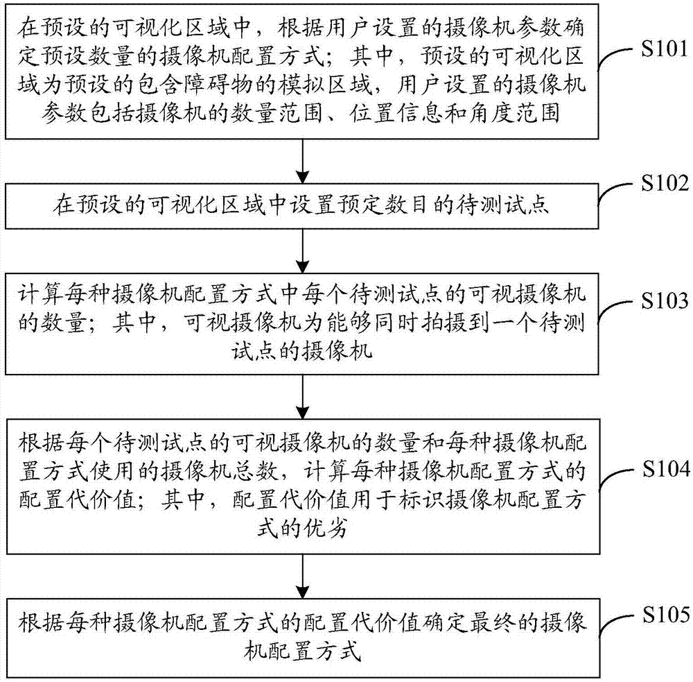
[0032] figure 1 It is a flowchart of a camera configuration method provided in Embodiment 1 of the present invention. The execution subject of this embodiment may be a computer device or a functional unit in the computer device. This embodiment specifically includes steps S101 to S105, which are described in detail as follows:
[0033] S101. In the preset visualization area, determine a preset number of camera configuration methods according to the camera parameters set by the user; wherein, the preset visualization area is a preset simulation area containing obstacles, and the camera parameters set by the user include camera Quantity range, position information and angle range of .
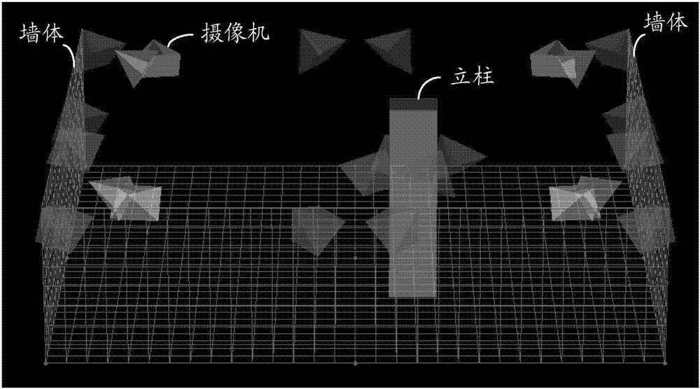
[0034] The preset visualization area can be any size created by the user in the optical motion capture system, and contains the simulated area of obstacles such as columns and walls. In the preset visualization area, users can further set camera parameters, including camera number range, posit...
Embodiment 2
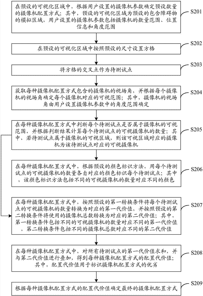
[0053] image 3 It is a flowchart of a camera configuration method provided in Embodiment 2 of the present invention. The execution subject of this embodiment may be a computer device or a functional unit in the computer device. This embodiment specifically includes steps S201 to S209, which are described in detail as follows:
[0054] S201. In the preset visualization area, determine a preset number of camera configuration methods according to camera parameters set by the user; wherein, the preset visualization area is a preset simulation area containing obstacles, and the camera parameters set by the user include camera Quantity range, position information and angle range of .
[0055] The preset visualization area can be any size created by the user in the optical motion capture system, and contains the simulated area of obstacles such as columns and walls. In the preset visualization area, users can further set camera parameters, including camera number range, position ...
Embodiment 3
[0106] Figure 7 It is a schematic structural diagram of a camera configuration device provided in Embodiment 3 of the present invention. For convenience of description, only parts related to the embodiment of the present invention are shown. Figure 7 An exemplary camera configuration apparatus may be an execution body of the camera configuration method provided in Embodiment 1, which may be a computer device or a functional unit in the computer device. Figure 7 An exemplary camera configuration device includes: an initialization module 31 , a test point setting module 32 , a quantity calculation module 33 , a cost calculation module 34 and a selection module 35 . The detailed description of each functional unit is as follows:
[0107] The initialization module 31 is used to determine a preset number of camera configurations according to the camera parameters set by the user in the preset visualization area; wherein, the preset visualization area is a preset simulation area...
PUM
 Abstract
Description
Claims
Application Information
 - R&D
- Intellectual Property
- Life Sciences
- Materials
- Tech Scout
- Unparalleled Data Quality
- Higher Quality Content
- 60% Fewer Hallucinations
Browse by: Latest US Patents, China's latest patents, Technical Efficacy Thesaurus, Application Domain, Technology Topic, Popular Technical Reports.
© 2025 PatSnap. All rights reserved.Legal|Privacy policy|Modern Slavery Act Transparency Statement|Sitemap|About US| Contact US: help@patsnap.com