
Motor device for fixing driving magnet

A fixed drive and motor technology, applied in the direction of magnetic circuit rotating parts, magnetic circuit shape/style/structure, etc., can solve the problems of drive magnet deviation, looseness, loss, drive magnet flying off, etc., to reduce maintenance probability and ensure quality Effect

Inactive Publication Date: 2017-08-29
南通同德电气设备有限公司
View PDF0 Cites 0 Cited by
  • Summary
  • Abstract
  • Description
  • Claims
  • Application Information

AI Technical Summary

Problems solved by technology

[0002] In the motor device used as a pump device, when a sharp rotation occurs, the loss and looseness caused by friction will cause the drive magnet to be unable to withstand the loss for a long time, and the drive magnet may have deviation and looseness
When the above looseness occurs, due to the centrifugal force, the driving magnet will fly off directly, resulting in failure, thus wasting the workload and maintenance costs

Method used


Image

  • Motor device for fixing driving magnet
  • Motor device for fixing driving magnet
  • Motor device for fixing driving magnet

Examples


Embodiment Construction

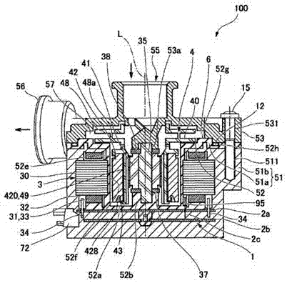
[0011] In the motor of this embodiment, since the engaging portion 445 covering the other end surface 422 of the driving magnet 42 is formed on the front end portion 440 of the magnet mounting portion 44 , axial movement of the driving magnet 42 can be reliably prevented. In addition, since the anti-idling convex portion 45a of the seat portion 45 fits in the anti-idling concave portion 42a formed on the one end surface 421 of the driving magnet 42, the driving magnet 42 can be reliably prevented from rotating around the axis. On the side of the seat 45, the small-diameter portion 426a of the driving magnet 42 is surrounded by the cylindrical portion 455 provided on the seat 45 itself to prevent the scattering of the driving magnet 42; A magnet scattering preventing concave portion 428 is provided radially outward from the inner peripheral edge, and a magnet scattering preventing convex portion fitted in the magnet scattering preventing concave portion 428 is formed on the seat...


PUM


Abstract

A motor device for fixing a driving magnet is used in a motor of a pump device, and a position, near to an outer side of an inner peripheral edge in a radius direction, on an end surface (422) of the other side of the driving magnet (42) and a protruding groove are embedded to form fixing.

Description

technical field [0001] The present invention relates to a motor device for stationary driving magnets. Background technique [0002] In the motor device used as a pump device, when rapid rotation occurs, the loss and looseness caused by friction will cause the drive magnet to be unable to withstand the loss for a long time, and the drive magnet may have deviation and looseness. When the above-mentioned looseness occurs, due to the centrifugal force, the drive magnet will fly off directly, thereby causing a malfunction, thereby wasting the workload and maintenance costs. Contents of the invention [0003] The present invention is made in view of the above problems, and its purpose is to provide a driving magnet that can firmly maintain normal operation when the driving magnet is loose or even fly off due to centrifugal force. [0004] In order to solve the above-mentioned technical problems, in the present invention, the motor device includes: a stator and a rotor, the rot...

Claims


Application Information

Patent Timeline
Patent Type & Authority Applications(China)
IPC IPC(8): H02K1/22H02K1/28
CPCH02K1/22H02K1/28
Inventor 徐学明
Owner 南通同德电气设备有限公司
Learn More