Portable welding machine

A portable, welding machine technology, applied in welding accessories and other directions, can solve the problems of increased difficulty in the handling process, long welding lines, and reduced use efficiency, and achieves the effect of automatic wire take-up, reasonable structure design, and wide use

Inactive Publication Date: 2017-08-22
ANHUI PULUN INTELLIGENT EQUIP CO LTD
View PDF7 Cites 4 Cited by
  • Summary
  • Abstract
  • Description
  • Claims
  • Application Information

AI Technical Summary

Problems solved by technology

[0002] The welding machine is an important equipment that is indispensable in the process of processing. Most of the electric welding machines and welding wires on the market now use a split structure. The length of the welding wire is generally longer. Finally, manual coiling is required, which is very troublesome, and because the welding machines in the factory are bulky and heavy, they may have to be moved to other places for work during the processing process, which increases the difficulty of the handling process
[0003] In the current technical means, there is a take-up wheel on the outer side of the welder's shell to take up the wire, but most of them use the handle to rotate the wire. If the welding wire is too long, it is easy to gather at the take-up wheel and cause the wire to be taken up. The wire effect is not good, which does not reduce people's labor, and it is not more troublesome than manual coiling; for the convenience of transportation, some wheels are installed at the bottom of the welding machine, and a push handle is installed at the top of the welding machine, but this undoubtedly increases The space occupied by the welding machine is too large, and it is not convenient to place the welding machine. In the factory where the space utilization rate is high, the use efficiency is seriously reduced.

Method used


Image

  • Portable welding machine
  • Portable welding machine
  • Portable welding machine

Examples


Embodiment Construction

[0016] In order to make the technical means, creative features, goals and effects achieved by the present invention easy to understand, the present invention will be further elaborated below.

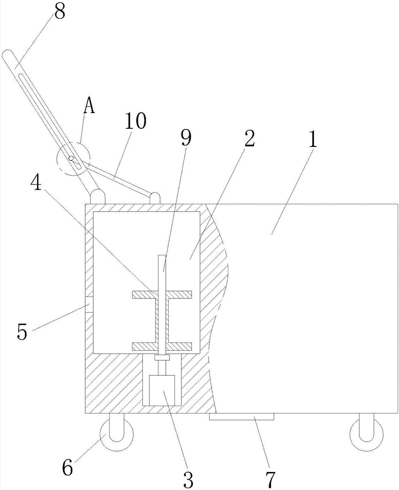
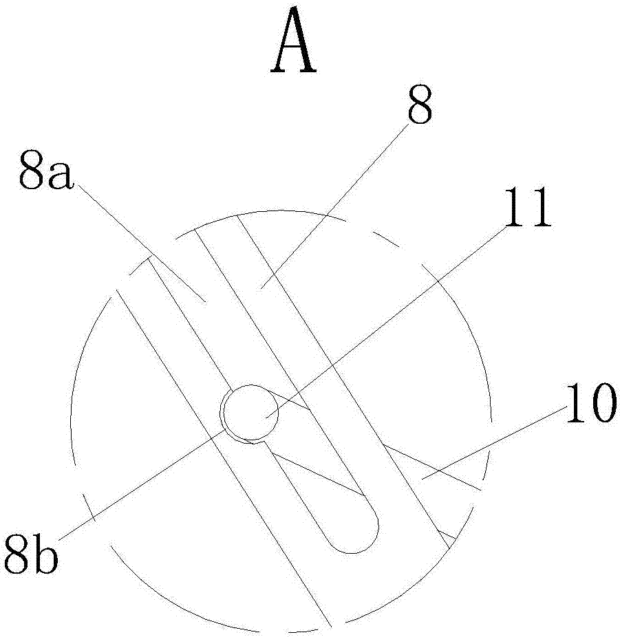
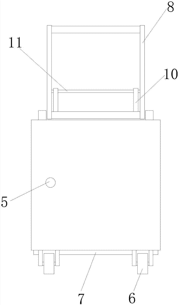
[0017] Such as Figure 1 to Figure 3 As shown, a portable welding machine includes a welding machine housing 1, a welding machine is installed in the welding machine housing 1, a cavity 2 is arranged in the welding machine housing 1, and a cavity 2 is installed at the bottom of the cavity 2 Motor 3, the motor 3 is connected with a take-up wheel 4, the bottom of the welding machine housing 1 is equipped with a wheel 6, the bottom of the welding machine housing 1 is fixed with a wear plate 7, the welding machine A push rod 8 is mounted on the top of the housing 1 .

[0018] Preferably, a lead screw 9 is installed on the motor 3 , and the lead screw 9 is installed on the take-up wheel 4 . In this manner, the welding wires can be evenly distributed on the take-up wheel during the winding-...


PUM


Abstract

The invention relates to a portable welding machine. The portable welding machine comprises a welding machine shell. A welding machine body is installed in the welding machine shell. A cavity is arranged in the welding machine shell. A motor is installed at the bottom of the cavity. The motor is connected with a lead screw provided with a take-up wheel. The left end face of the welding machine shell is provided with a weld wire hole. Wheels are installed at the bottom of the welding machine shell. A wear-proof plate is fixedly installed at the bottom of the welding machine shell. A push rod is installed on the upper portion of the welding machine shell. The motor drives the take-up well to achieve automatic taking up. The foldable type push rod can be stored in the welding machine shell when not used. The wear-proof plate is arranged at the bottom of the welding machine shell, so that the welding machine shell cannot be damaged when passing by barriers. The portable welding machine is reasonable in structural design and convenient to use; the automatic take-up process is achieved, and the take-up effect is good; and compared with the product of the same type, the portable welding machine is smaller in size, convenient to transport and wide in application range.

Description

technical field [0001] The invention relates to the field of spot welding processing and manufacturing equipment, in particular to a portable welding machine. Background technique [0002] The welding machine is an important equipment that is indispensable in the process of processing. Most of the electric welding machines and welding wires on the market now use a split structure. The length of the welding wire is generally longer. Finally, manual coiling is required, which is very troublesome, and because the welding machines in the factory are bulky and heavy, they may have to be moved to other places for work during the processing process, which adds difficulty to the handling process. [0003] In the current technical means, there is a take-up wheel on the outer side of the welder's shell to take up the wire, but most of them use the handle to rotate the wire. If the welding wire is too long, it is easy to gather at the take-up wheel and cause the wire to be taken up. T...

Claims


Application Information

Patent Timeline
Patent Type & Authority Applications(China)
IPC IPC(8): B23K9/32
CPCB23K9/32
Inventor 谭铁龙
Owner ANHUI PULUN INTELLIGENT EQUIP CO LTD
Why Eureka
Try Eureka