
Vacuum drying device

A technology of vacuum drying device and vacuum chamber, which is applied in the direction of dry cargo handling, drying solid materials, local agitation dryers, etc. It can solve the problems of poor contact point formation between the display substrate and the support column, and achieve a solution to the poor contact point formation Effect

Active Publication Date: 2017-08-18
BOE TECH GRP CO LTD +1
View PDF6 Cites 4 Cited by
  • Summary
  • Abstract
  • Description
  • Claims
  • Application Information

AI Technical Summary

Problems solved by technology

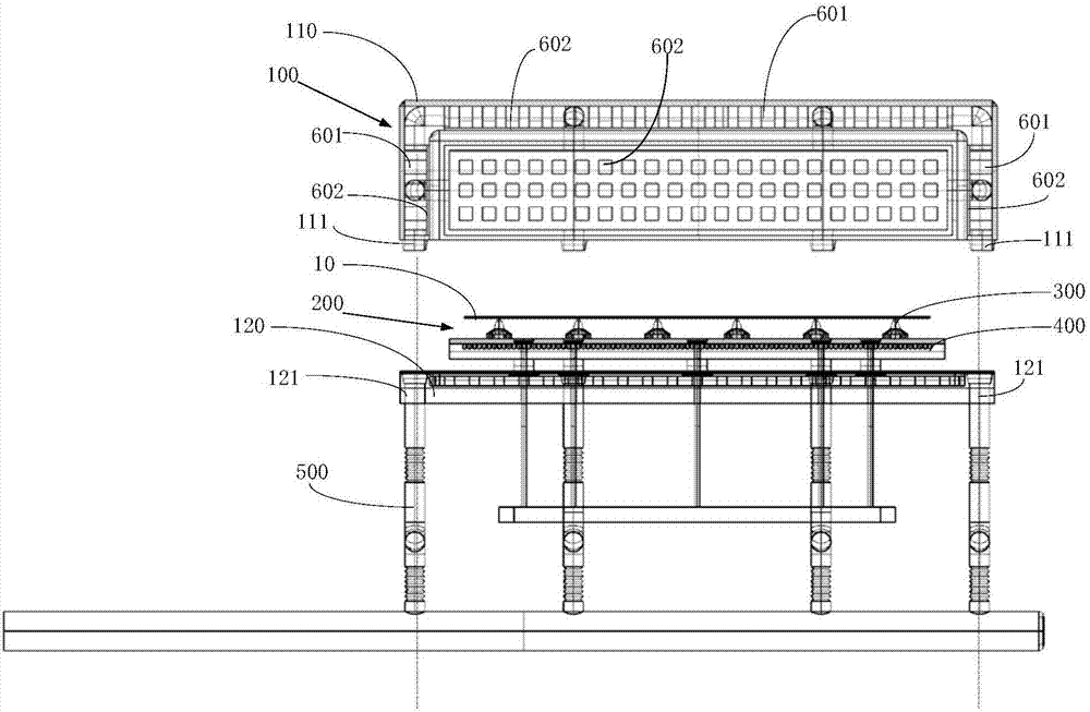
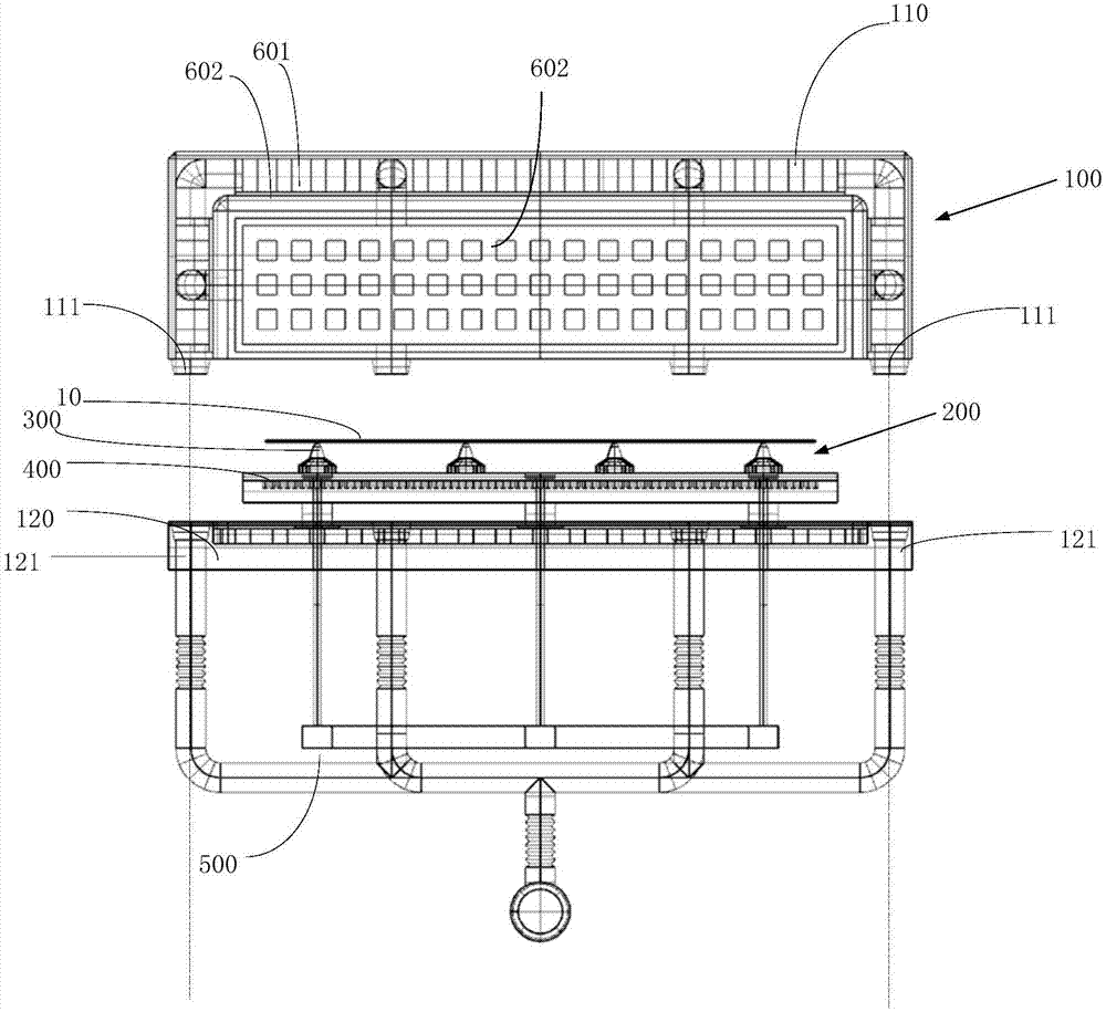
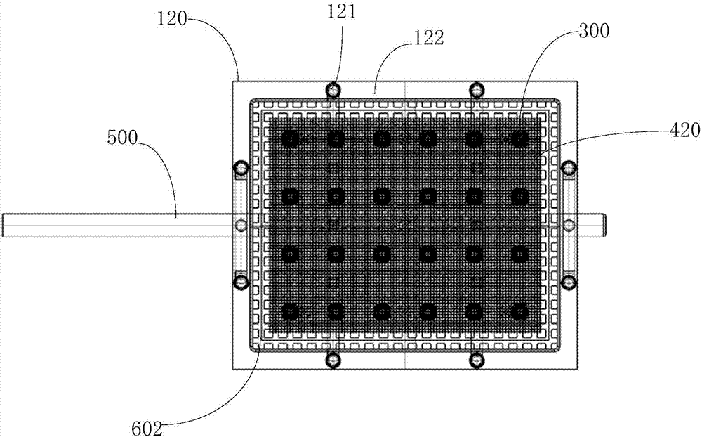
[0003] The purpose of the present invention is to provide a vacuum drying device, the supporting part set on the carrying platform can be moved, so as to change the contact position with the substrate, so as to solve the problem in the prior art that the contact point between the display substrate and the support column is poorly formed question

Method used


Image

  • Vacuum drying device
  • Vacuum drying device
  • Vacuum drying device

Examples


Embodiment Construction

[0039] In order to make the purpose, technical solutions and advantages of the embodiments of the present invention more clear, the following will clearly and completely describe the technical solutions of the embodiments of the present invention in conjunction with the drawings of the embodiments of the present invention. Apparently, the described embodiments are some, not all, embodiments of the present invention. All other embodiments obtained by those skilled in the art based on the described embodiments of the present invention belong to the protection scope of the present invention.

[0040] Aiming at the technical problem that the supporting column on the carrying platform of the vacuum drying device in the prior art is fixed and cannot be moved, and defects are easily formed at the contact point between the supporting column and the substrate, the present invention provides a vacuum drying device, the carrying platform of which The provided support member can be moved ...


PUM


Abstract

The invention provides a vacuum drying device. The vacuum drying device comprises a vacuum chamber and a bearing table which is arranged in the vacuum chamber and is used for bearing a to-be-treated object, wherein the bearing table comprises a bearing platform, a plurality of supporting parts arranged on the bearing platform, and a moving mechanism which can move the supporting parts. According to the vacuum drying device provided by the invention, the supporting parts arranged on the bearing table can be moved, contact positions of the supporting parts and a substrate can be changed, and the problem that in the prior art, contact points of a display substrate and supporting pillars are badly formed is solved.

Description

technical field [0001] The invention relates to the technical field of display manufacturing, in particular to a vacuum drying device. Background technique [0002] In the manufacturing process of products such as displays, it is usually necessary to use a vacuum drying device to process the substrate. Wherein, taking the vacuum drying device in the prior art as an example, it includes a vacuum chamber, and a carrying platform for carrying a glass display substrate is arranged in the vacuum chamber, and a supporting column for carrying the substrate is usually arranged on the carrying platform. Since the supporting columns on the carrying platform of the vacuum drying device in the prior art are fixed, the supporting position of the display substrate cannot be changed. When vacuuming, the display substrate will bear a relatively large downward pressure. The contact point of the support column is easy to form a defect, and it is difficult to completely solve this defect. C...

Claims


Application Information

Patent Timeline
Patent Type & Authority Applications(China)
IPC IPC(8): F26B9/06F26B25/00
CPCF26B9/06F26B25/00F26B25/003
Inventor 向琛邸阳渠谦徐钟国
Owner BOE TECH GRP CO LTD
Learn More