
A reinforced concrete column with a core column and replaceable parts at the failure site

A reinforced concrete column and reinforced concrete technology, applied in columns, pillars, piers and other directions, can solve the problems of low bearing reliability and difficult repair, and achieve the effects of reducing repair work, delaying the rate of stiffness degradation, and improving energy dissipation capacity.

Active Publication Date: 2019-02-05
HUNAN YUBAN CONSTR GRP CO LTD
View PDF5 Cites 0 Cited by
  • Summary
  • Abstract
  • Description
  • Claims
  • Application Information

AI Technical Summary

Problems solved by technology

[0006] The technical problem to be solved by the present invention is to solve the problem that the bearing reliability of the reinforced concrete column designed according to the current method is lower than the expected level under the action of horizontal load (wind or earthquake) and it is difficult to repair after damage. Reinforced Concrete Columns with Core Columns and Replaceable Parts

Method used


Image

  • A reinforced concrete column with a core column and replaceable parts at the failure site
  • A reinforced concrete column with a core column and replaceable parts at the failure site
  • A reinforced concrete column with a core column and replaceable parts at the failure site

Examples


Embodiment 1

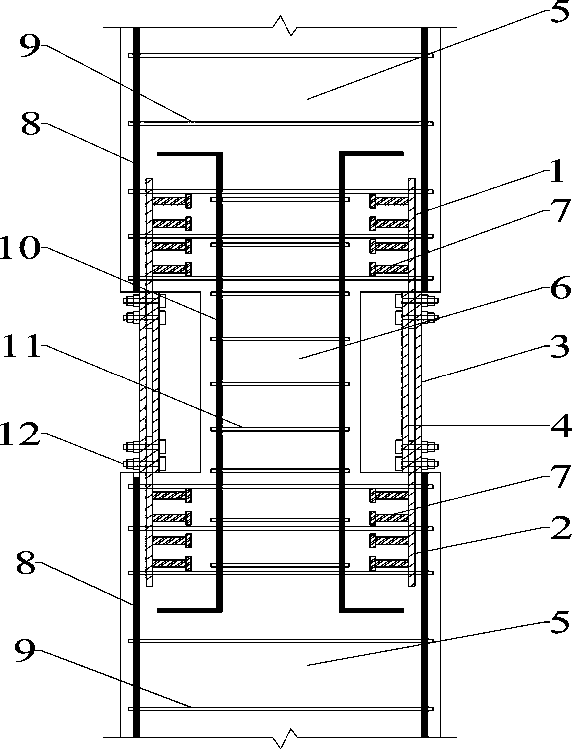
[0043] refer to figure 1 , figure 2 , Figure 4 , Figure 6 , Figure 8 , Figure 10 , a reinforced concrete column with a core column and replaceable parts arranged at the failure position, including a reinforced concrete column body 5, and at least one section of a reinforced concrete core column 6, both ends of the reinforced concrete core column 6 are fixed to the reinforced concrete column body 5 Even, the cross-sectional dimension of the reinforced concrete core column 6 is smaller than the cross-sectional dimension of the reinforced concrete column body 5;

[0044] The reinforced concrete column also includes at least one pre-embedded steel pipe group and at least one replaceable component group. The number of pre-embedded steel pipe groups and the number of replaceable component groups are the same as the number of sections of the reinforced concrete core column. Each section of the reinforced concrete core column Corresponding to a pre-embedded steel pipe group ...

Embodiment 2

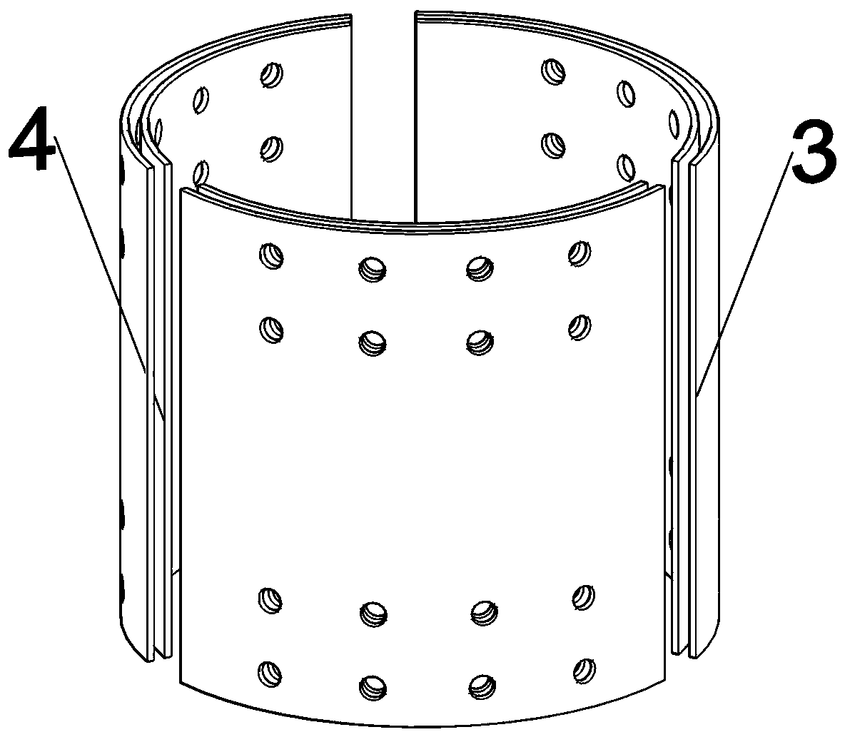
[0062] refer to image 3 , Figure 5 , Figure 7 , Figure 9 and Figure 11 , in this embodiment, the pre-embedded steel pipe is a hollow steel pipe with a circular cross section.

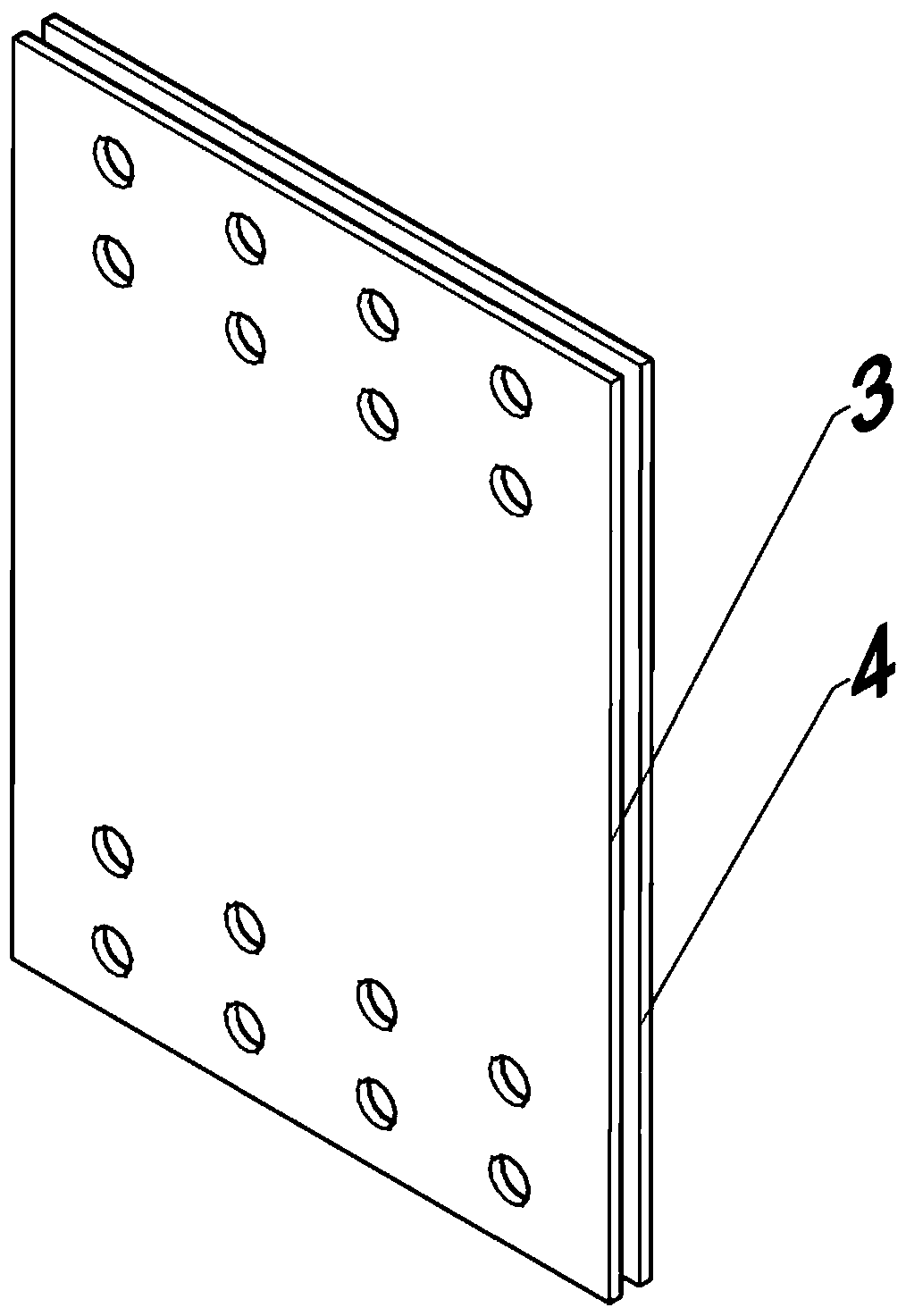
[0063] The cross-sectional shape of the embedded steel pipe is circular, and each replaceable part group may include two pairs of replaceable parts, or more than three pairs of replaceable parts. In this embodiment, the number of replaceable component groups is three pairs (see image 3 ). The guard plate is a curved guard plate, that is, the guard plate used as the inner replaceable part 4 and the outer replaceable part 3 is a curved guard plate.


PUM


Abstract

The invention discloses a reinforced concrete column for placing a core column and a replaceable component at a failed part. The reinforced concrete column comprises at least one section of a reinforced concrete core column as well as at least one preburied steel tube group and at least one replaceable component group, wherein two ends of the reinforced concrete core column are both fixedly connected with a reinforced concrete column body; the replaceable component group is arranged at the periphery of the reinforced concrete core column; each preburied steel tube group comprises an upper preburied steel tube and a lower preburied steel tube; the upper end of the upper preburied steel tube and the lower end of the lower preburied steel tube are both buried into the reinforced concrete column body; the lower end of the preburied steel tube and the upper end of the lower preburied steel tube extend outside the reinforced concrete column body; the lower end of the upper preburied steel tube and the upper end of the lower preburied steel tube are detachably connected with two ends of the replaceable component group. By adopting the reinforced concrete column, the replaceable component group is arranged at the failed part, then the energy consumption of a plastic hinge at the failed part can be remarkably improved, the rigidity degradation velocity of the plastic hinge can be retarded, the plastic deformation is concentrated on the replaceable component group, and then repairing operation after damage can be reduced.

Description

technical field [0001] The invention belongs to the field of building structures, and in particular relates to a reinforced concrete column with a core column and a replaceable part arranged at a failure position. Background technique [0002] With the continuous advancement of basic theory and technology and the popularization and application of high-performance materials, people have higher and higher requirements for the performance of structures. The structure has gradually changed from limit state design to recoverable function design, in order to minimize the loss. Lu Xilin et al. mentioned in "Research Progress of Structural Systems with Replaceable Components" that by installing replaceable components in key parts of the structural system, rapid repair and replacement of damaged parts can be achieved. Replaceable parts are generally installed in parts of the structure that are prone to plastic deformation, and these parts are replaced with high-ductility materials an...

Claims


Application Information

Patent Timeline
Patent Type & Authority Patents(China)
IPC IPC(8): E04C3/34
CPCE04C3/34
Inventor 蒋友宝周浩
Owner HUNAN YUBAN CONSTR GRP CO LTD
Learn More