
Portable electric stamping device

A stamper, portable technology, applied in stamping, printing, etc., can solve problems such as arthritis, large stamping pressure, deformed growth, etc.

Active Publication Date: 2017-08-18
深圳市华海科技研发有限公司
View PDF6 Cites 2 Cited by
  • Summary
  • Abstract
  • Description
  • Claims
  • Application Information

AI Technical Summary

Problems solved by technology

Some full-time stampers stamp hundreds to thousands of times a day, which can cause soreness in wrists and arms in mild cases, and arthritis, deformed growths and other diseases in severe cases.
[0004] Chinese patent application 201610961771.6 announced a "labor-saving stamper", which uses the energy stored in the manual compression spring to generate inertial force when it is released, which is superimposed with the pressure of the human hand, thereby generating a greater stamping pressure and achieving labor-saving stamping However, it still requires a certain amount of pressure from the hands, and after a large increase in the number of operations, there will still be a certain sense of fatigue

Method used


Image

  • Portable electric stamping device
  • Portable electric stamping device
  • Portable electric stamping device

Examples


Embodiment 1

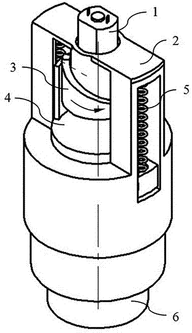
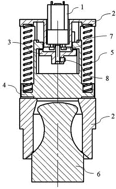
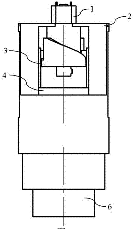
[0031] see figure 1 , figure 2 , image 3 , Figure 4 , Figure 5 and Figure 7 . The positioning surface 11 of the driver 1 is loaded into the first installation hole 22 of the frame 2, the end surface 12 of the driver 1 is in contact with the first installation surface 21 of the frame 2, and the driver 1 is fixed to the frame by two first screws 7. on shelf 2. The fourth mounting hole 34 of the cam 3 is mounted on the shaft 13 of the driver 1, and the cam 3 is fixed on the driver 1 by the second screw 8.

[0032] see figure 2 , Figure 4 , Figure 6 , Figure 7 , Figure 8 , Figure 9 and Figure 10 . The lifting surface 41 of the hammer head 4 is located above the spiral surface 31, the top surface 32 and the second bottom surface 35 of the cam 3, and the upper end of the spring 5 is installed in the second mounting hole 23 of the frame 2 and contacts the second mounting surface 24. , the spring 5 has a smaller diameter, and the lower end of the spring 5 is...

Embodiment 2

[0036] see Figure 12 It is a schematic diagram of Embodiment 2 of the present invention. The spring 5 is a large-diameter type, and the number is one. The outer diameter of the spring 5 is greater than the outer diameter of the cam 3, concentric with the cam 3, and located between the hammer head 4 and the frame 2, and the rest are the same as in the embodiment One is similar, so I won't repeat them.

Embodiment 3

[0038] see Figure 13 It is a driver control circuit diagram of the present invention, the driver 1, the power supply 10 and the controller 9 are connected in series, the driver 1 is powered on when the controller 9 is turned on, and the driver 1 is powered off when the controller 9 is turned off.

[0039] In the present invention, "first", "second", "upper", "lower", "larger", "smaller" and the like are for distinction in description, and have no other special meanings.


PUM


Abstract

The invention discloses a portable electric stamping device which comprises a driver, a rack, a cam, a hammer, a spring, a first screw, a second screw, a controller and a power supplier. In the stamping process, an existing stamp is placed into the electric stamping device, the controller only needs to be triggered slightly with the human hand, and the clean stamping effect can be obtained; and when stamping needs to be carried out many times, too large fatigues and muscle strains of the wrist and the arm of a person can be avoided, the daily work of people is greatly facilitated, and body health of people is facilitated.

Description

technical field [0001] The invention relates to the field of stationery, in particular to a portable electric stamper. Background technique [0002] A seal is a tool that people use to print on documents or objects to express identification, approval, confirmation, identification or signature. When stamping, a certain pressure is required between the seal and the document or item to make the printed text clear. [0003] Generally, small seals can be stamped clearly without too much force when stamping. Larger seals, due to their large area, must use greater force or even use both hands to stamp clearly. Some full-time stamping staff stamp hundreds to thousands of times a day, which can cause sore wrists and arms in mild cases, and arthritis, deformed growths and other diseases in severe cases. [0004] Chinese patent application 201610961771.6 announced a "labor-saving stamper", which uses the energy stored in the manual compression spring to generate inertial force when ...

Claims


Application Information

Patent Timeline
Patent Type & Authority Applications(China)
IPC IPC(8): B41K3/04B41K3/62
CPCB41K3/04B41K3/62
Inventor 金世华
Owner 深圳市华海科技研发有限公司
Learn More