Dyeing cloth gradual flattening equipment
A cloth and equipment technology, which is applied in the field of progressive smoothing equipment for dyed cloth, can solve the problems of not having the function of smoothing the cloth surface, and achieve the effect of good effect, large contact area and large friction force
- Summary
- Abstract
- Description
- Claims
- Application Information
AI Technical Summary
Problems solved by technology
Method used
Image
Examples
Embodiment 1
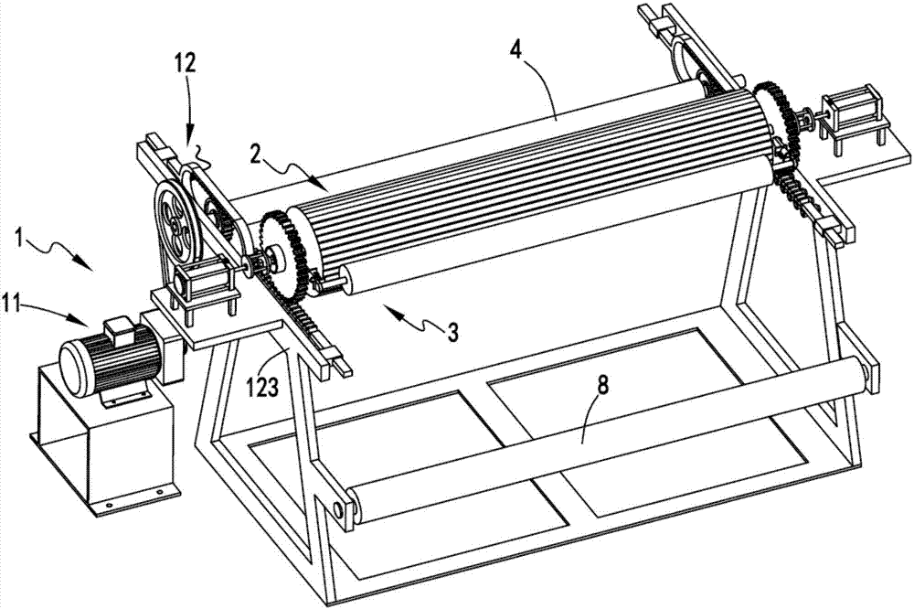
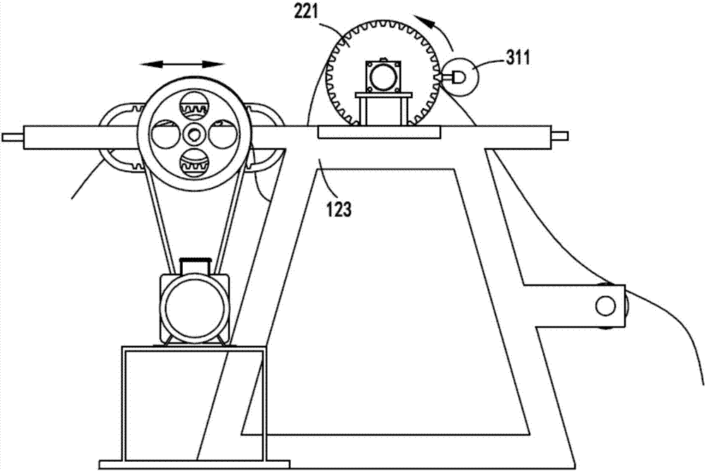
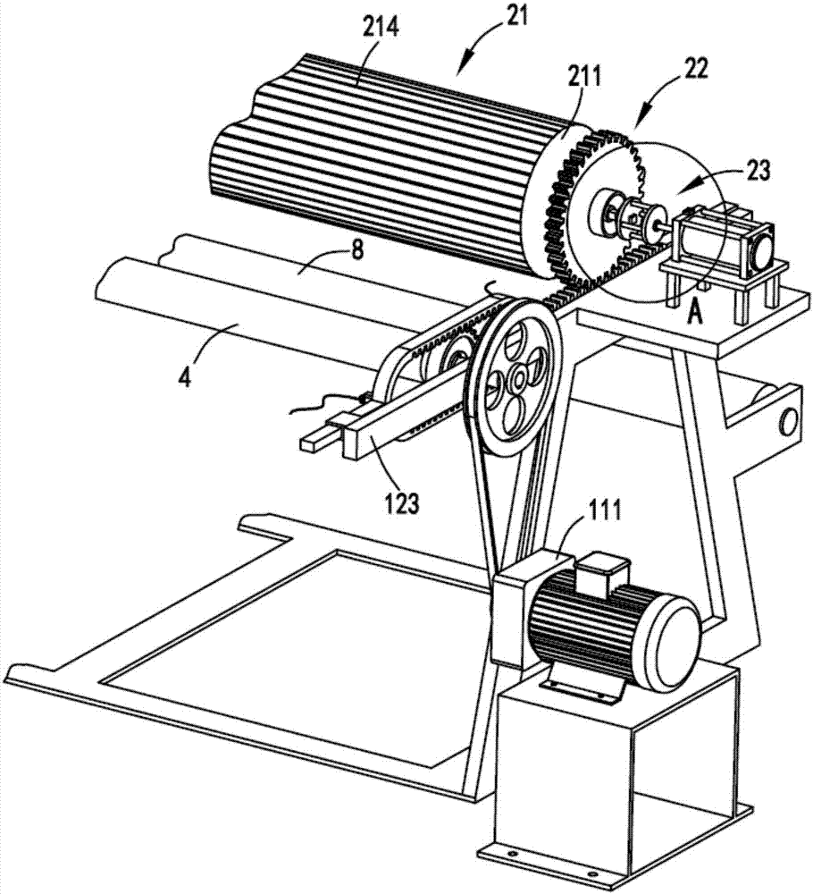
[0039] figure 1 Schematic diagram of the progressive smoothing equipment for dyed fabrics, figure 2 Schematic diagram of the front view of the progressive smoothing equipment for dyed fabrics, image 3 It is a partial structural diagram of the progressive smoothing equipment for dyed fabrics, Figure 4 It is a schematic diagram of the enlarged structure of the driving device and the switching device, Figure 5 It is a schematic diagram of the transmission device and the smoothing mechanism, Image 6 is the schematic diagram of the transmission device, Figure 7 Schematic diagram of the enlarged structure of the adjustment device, Figure 8 is a schematic diagram of the extrusion, Figure 9 It is a schematic diagram of the structure of the ring and the drive. Such as figure 1 , figure 2 , image 3 , Figure 4 , Figure 5 , Image 6 , Figure 7 , Figure 8 with Figure 9 As shown, a dyed cloth progressively smoothing equipment includes a power mechanism 1, the p...
Embodiment 2
[0055] Such as figure 1 , figure 2 , image 3 , Figure 4 , Figure 5 , Image 6 , Figure 7 , Figure 8 with Figure 9 As shown, the components that are the same as or corresponding to those in the first embodiment are marked with the corresponding reference numerals in the first embodiment. For the sake of simplicity, only the differences from the first embodiment will be described below. The difference between the second embodiment and the first embodiment is that two sets of the driving member 113 and the transmission device 12 are symmetrically arranged, and the driving member 113 and the driving member 113 are connected by a guide roller 4 .
[0056] The set guide roller 4 can be driven by the motor to rotate along the direction of cloth transmission. After the cloth passes through the guide roller 4, it is transmitted to the carrying roller 211. Due to the rotation of the guide roller 4 and the rotation is continuous The rotation of the carrying roller 211 is d...
PUM
 Abstract
Description
Claims
Application Information
 - R&D
- Intellectual Property
- Life Sciences
- Materials
- Tech Scout
- Unparalleled Data Quality
- Higher Quality Content
- 60% Fewer Hallucinations
Browse by: Latest US Patents, China's latest patents, Technical Efficacy Thesaurus, Application Domain, Technology Topic, Popular Technical Reports.
© 2025 PatSnap. All rights reserved.Legal|Privacy policy|Modern Slavery Act Transparency Statement|Sitemap|About US| Contact US: help@patsnap.com


