A disc connecting rod automatic welding machine

An automatic welding machine and connecting rod technology, which is applied in welding equipment, auxiliary welding equipment, welding/cutting auxiliary equipment, etc., can solve the problems of inaccurate ring position, high welding error rate, and inconsistent weld width, etc., to achieve Automatic operation, uniform surface radian and uniform weld width

Inactive Publication Date: 2019-10-08
济南鎏佳机械有限公司
View PDF7 Cites 0 Cited by
  • Summary
  • Abstract
  • Description
  • Claims
  • Application Information

AI Technical Summary

Problems solved by technology

[0005] 1. Due to human influence, it is difficult to accurately locate the position of the ring and ensure that the ring is perpendicular to the central axis of the connecting rod during the welding process. As a result, the position of the welded ring is often not accurate enough, and the angle of the ring relative to the central axis of the connecting rod varies. Not the same, the field of use that requires precision for disc connecting rods tends to have a high scrap rate
[0006] 2. Due to the effect of hand-holding or other factors, the vibration problem of the connecting rod cannot be well solved during the welding process. The ring will vibrate with the vibration of the connecting rod, so that the welded seam is often of inconsistent width and the surface of the weld seam The arc is uneven and the consistency of the weld is poor, resulting in poor welding quality of the welded product and affecting sales
[0007] 3. Due to the large production volume of the disc connecting rod, it is impossible to realize the automatic welding of the connecting rod. The labor intensity of manual welding and manually supporting the connecting rod or rotating the connecting rod is high. The eyes and physical strength of the long-term welding operation are easy to fatigue, resulting in welding errors high rate

Method used


Image

  • A disc connecting rod automatic welding machine
  • A disc connecting rod automatic welding machine
  • A disc connecting rod automatic welding machine

Examples


Embodiment Construction

[0030] The present invention will be described in further detail below in conjunction with the accompanying drawings and examples. The following examples are only descriptive, not restrictive, and cannot limit the protection scope of the present invention.

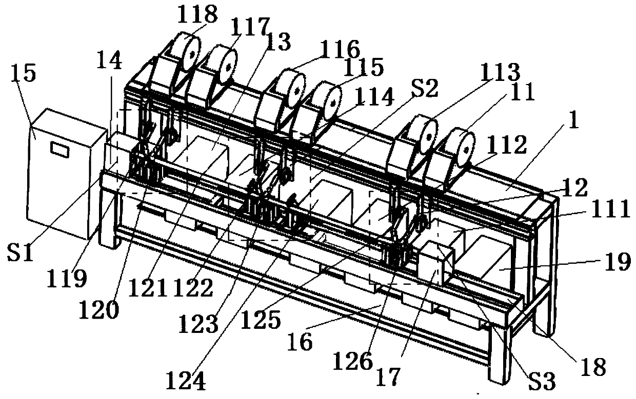
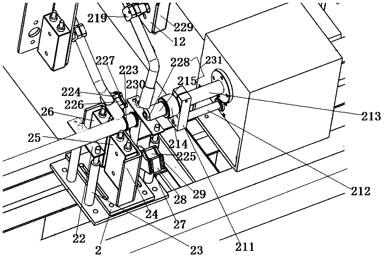
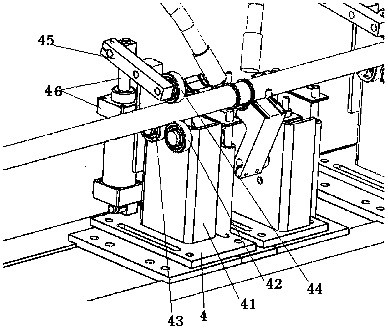
[0031] figure 1 It is the schematic diagram of the disc connecting rod automatic welding machine described in the present invention; figure 2 for figure 1 Partial enlarged schematic diagram of the area shown in S3; image 3 for figure 1 Partial enlarged schematic diagram of the area shown in S2; Figure 4 for figure 1 The local enlarged schematic diagram of the region shown in S1. like Figure 1-Figure 4 As shown, the present invention provides a disc connecting rod automatic welding machine, including a frame, a tooling clamping mechanism, a workpiece positioning and clamping mechanism, a welding torch lifting mechanism, a welding torch and a connecting rod 121, and the frame is fixed with The tooling clamping mecha...


PUM


Abstract

The invention discloses an automatic disc connecting rod welding machine. The automatic welding machine comprises a machine frame, a workpiece clamping mechanism, a workpiece positioning and clamping mechanism, a welding gun lifting mechanism, a welding gun and a connecting rod; the workpiece clamping mechanism capable of abutting against the connecting rod, the workpiece positioning and clamping mechanism and the welding gun lifting mechanism are fixedly arranged on the machine frame; the workpiece clamping mechanism abuts against the connecting rod and drives the connecting rod to vertically rotate on the workpiece positioning and clamping mechanism; the workpiece positioning and clamping mechanism further comprises a compressing mechanism capable of preventing the connecting rod from vibrating when the connecting rod rotates; the welding gun is rotationally arranged on the welding gun lifting mechanism; the connecting rod is rotationally arranged on the workpiece positioning and clamping mechanism; and a plurality of circular rings are arranged on the connecting rod in a sleeving mode and are rotationally arranged on the workpiece positioning and clamping mechanism in an embedded mode in the direction perpendicular to the central axis of the connecting rod. The automatic circular ring connecting rod welding machine has the advantages that the welding labor intensity can be reduced, the welding production efficiency can be improved, the welding position of the circular rings can be accurate, and the quality of welding joints can be high.

Description

technical field [0001] The invention belongs to the technical field of welding equipment, and in particular relates to a disc connecting rod automatic welding machine. Background technique [0002] The disc connecting rod includes a connecting rod and a ring welded on the connecting rod. According to the actual use situation, according to the drawing of a certain specification, a ring is set on the connecting rod at a determined position, and the ring is placed on the connecting rod. Welding is made on the connecting rod. [0003] The ring connecting rod has a wide range of uses, such as being widely used in scaffolding and other equipment as a special component. [0004] At present, the production of circular connecting rods mostly adopts manual welding of circular rings or manual welding of circular rings combined with some rough machining equipment. This welding method often faces the following technical problems: [0005] 1. Due to human influence, it is difficult to a...

Claims


Application Information

Patent Timeline
Patent Type & Authority Patents(China)
IPC IPC(8): B23K37/04B23K37/047B23K37/02
Inventor 庄聿翔
Owner 济南鎏佳机械有限公司
Why Eureka
Try Eureka