Eureka AIR delivers breakthrough ideas for toughest innovation challenges, trusted by R&D personnel around the world.

A pile foundation static load test system

A technology of static load test and pile foundation, which is applied in the test of foundation structure, foundation structure engineering, construction, etc. It can solve problems such as weight block slipping, ballast center of gravity imbalance, affecting detection accuracy, etc., and achieve easy control of ballast body balance performance, improving resource utilization, and the effect of test process safety

Active Publication Date: 2019-02-05
WENZHOU XINDA TRAFFIC ENG TEST DETECTION
View PDF10 Cites 1 Cited by
  • Summary
  • Abstract
  • Description
  • Claims
  • Application Information

AI Technical Summary

Problems solved by technology

[0003] The stacking method is to install a horizontal balance steel beam on the horizontal support girder, and then lay metal beams or concrete beams on the horizontal balance steel beam to form a load-bearing platform, and then stack the counterweight on the ballast load-bearing platform After the blocks form the ballast, carry out the static load detection test on the pile foundation; the difficulty in the detection test of the surcharge method in the prior art is that due to the large number of counterweights, deviations are likely to occur during the surcharge process, which in turn causes the center of gravity of the ballast to be out of balance , not only affects the detection accuracy, but also easily causes the counterweight to slip or the ballast to collapse, and the safety is low

Method used


Image

  • A pile foundation static load test system
  • A pile foundation static load test system
  • A pile foundation static load test system

Examples


Embodiment Construction

[0032] The present invention will be described in further detail below in conjunction with the accompanying drawings.

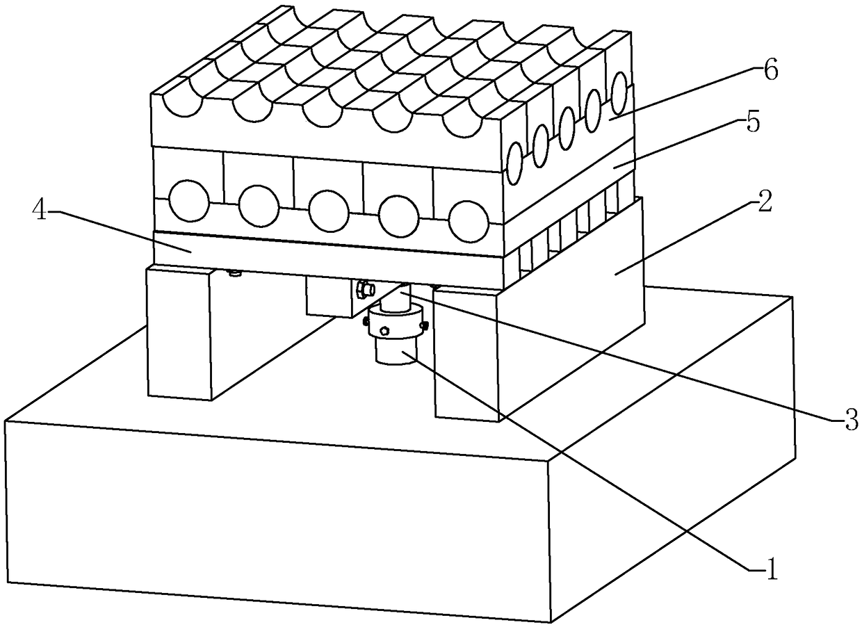
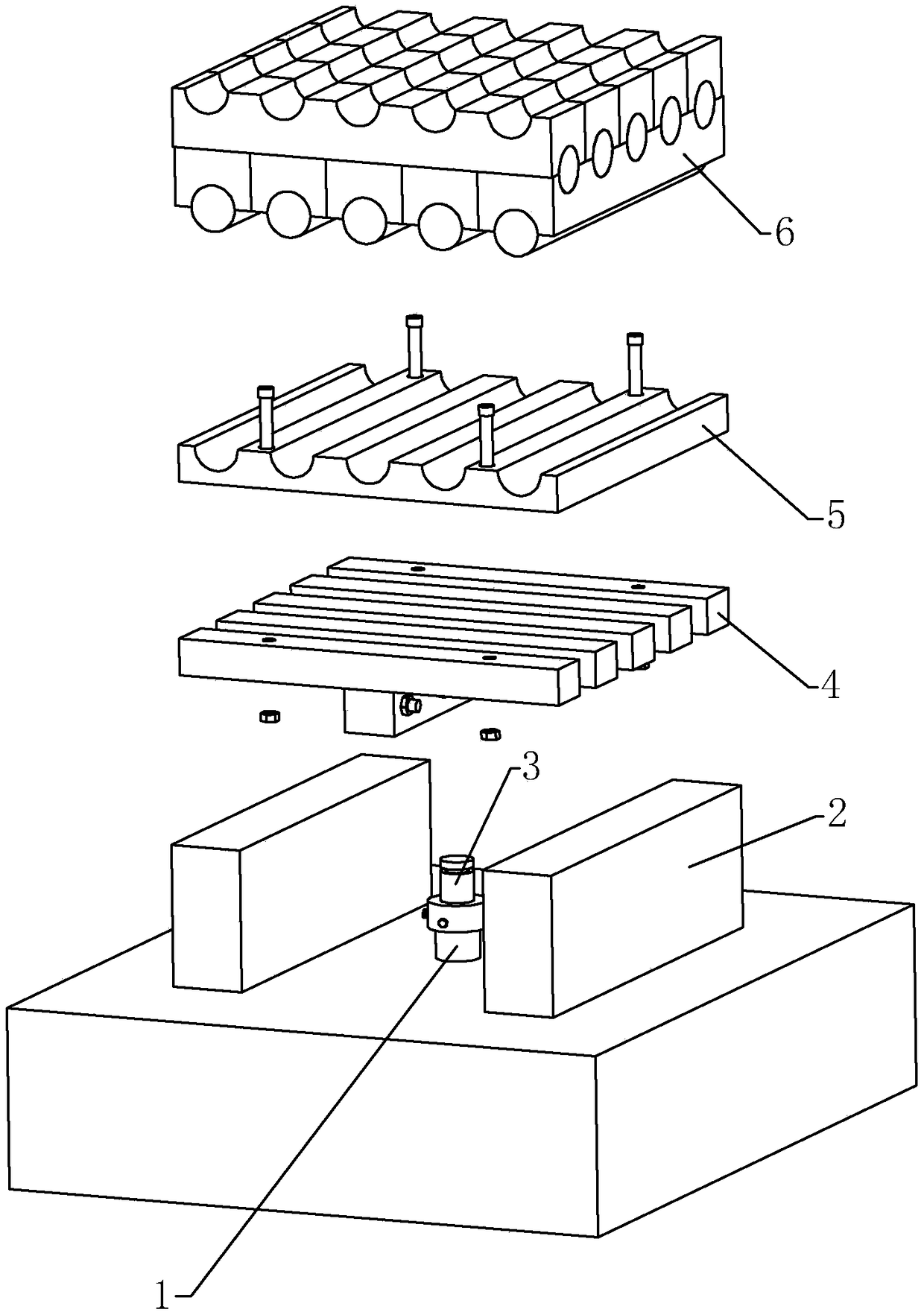
[0033] This embodiment discloses a pile foundation static load test system with surcharge method, such as figure 1 , 2 As shown, it includes a test pile 1 , a bearing wall 2 , a jack 3 , a reaction frame 4 , a bearing plate 5 and a counterweight 6 .

[0034] Such as image 3 As shown, the jack 3 is installed directly above the axis of the test pile 1, and the pile head of the test pile 1 is covered with a steel reinforcing cover 7, and combined with Figure 4 to Figure 6 , the overall shape of the reinforcement cover 7 is a cylindrical shape with a closed upper end, a positioning groove 8 is provided at the inner axis of the top wall of the reinforcement cover 7, and a positioning groove 8 is provided at the axis of the upper end surface of the test pile 1 to match the size of the positioning groove 8. The positioning round platform 9. The outer side of t...


PUM


Abstract

The invention discloses a pile foundation static load test system. The pile foundation static load test system comprises bearing walls, a jack, a counter-force frame and balancing weights. A secondary beam is fixedly connected with a bearing plate, and a plurality of containing grooves with semicircular cross sections are evenly distributed in the bearing plate in the directions where the two ends of the secondary beam are located with the jack as a center. The balancing weights include first balancing weights and second balancing weights. Each first balancing weight is of a cylindrical structure, and the radius of each first balancing weight is equal to that of each containing groove. The length of each second balancing weight and the length of the first balancing weight are the same, one side of each second balancing weight is also provided with containing grooves, the other side of each second balancing weight is provided with combination grooves perpendicular to the containing grooves, and the cross sections of the combination grooves are the same with those of the containing grooves. In the piling process of the balancing weights, the first balancing weights and the second balancing weights are alternatively piled according to the number of layers. The pile foundation static load test system can control the balance of a carrier more easily, and the test process is safer.

Description

technical field [0001] The invention relates to the technical field of pile foundation static load detection, and more specifically relates to a pile foundation static load test system. Background technique [0002] Static load test of pile foundation is an important part of engineering inspection. The most common method is the surcharge method for inspection, and the inspection results are more intuitive. [0003] The stacking method is to install a horizontal balance steel beam on the horizontal support girder, and then lay metal beams or concrete beams on the horizontal balance steel beam to form a load-bearing platform, and then stack the counterweight on the ballast load-bearing platform After the blocks form the ballast, carry out the static load detection test on the pile foundation; the difficulty in the detection test of the surcharge method in the prior art is that due to the large number of counterweights, deviations are likely to occur during the surcharge proces...

Claims


Application Information

Patent Timeline
Patent Type & Authority Patents(China)
IPC IPC(8): E02D33/00
CPCE02D33/00
Inventor 孙铁军郑锋利沈立中邓昭伟孟灵鑫王丹锋岑建武
Owner WENZHOU XINDA TRAFFIC ENG TEST DETECTION
Why Eureka
Eureka Blog
Learn More