Injection molding mold having anti-pressure-relief function

An injection mold and anti-leakage technology, which is applied in the field of molds, can solve the problems of high energy consumption, reduced service life, and failure to reach, and achieve the effects of simple device structure, improved service life, and energy saving

Inactive Publication Date: 2017-08-11
HUANGSHI HUAZHI MOLD CO LTD
View PDF0 Cites 0 Cited by
  • Summary
  • Abstract
  • Description
  • Claims
  • Application Information

AI Technical Summary

Problems solved by technology

[0002] The injection mold needs to maintain the pressure of the molten material in the cavity for a period of time during the cooling and solidification process of the workpiece injection molding. Premature pressure relief will cause the quality of the surface and internal structure of the workpiece to deteriorate, failing to meet the corresponding requirements.
The existing pressure maintaining method is to use the injection molding machine head to complete the injection molding work, stay at the pouring port, and wait for the workpiece to cool and solidify. This will cause the injection molding equipment to continue to be in a high-pressure state, and the internal hydraulic system will continue to heat up, resulting in a decrease in service life. Maintenance and repair costs, and high energy consumption

Method used


Image

  • Injection molding mold having anti-pressure-relief function
  • Injection molding mold having anti-pressure-relief function

Examples


Embodiment 1

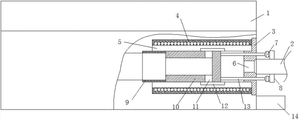
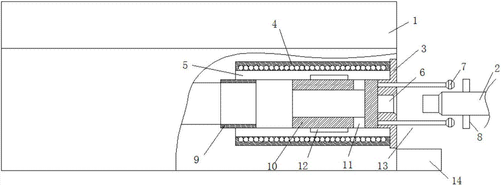
[0017] Such as Figure 1-2 As shown, an injection mold with anti-pressure relief function includes a mold main body 1 and a machine head 2, an electromagnetic chuck 8 is provided outside the injection port of the machine head 2, and a protective valve is provided inside the main channel of the mold main body 1. Pressure column 5, the outer side of the pressure holding column 5 is sleeved with the heating sleeve 4, the inside of the pressure holding column 5 is provided with an anti-pressure relief device, and the end of the pressure holding column 5 corresponding to the injection port of the machine head 2 is provided with a positioning method Lan 3, the center of the positioning flange 3 is provided with a pouring port 6 corresponding to the injection port of the machine head 2.

[0018] In this embodiment, the pressure relief device includes a one-way stem 10 and a push-pull rod 13, the one-way stem 10 is located inside the pressure-holding column 5, and the one-way stem 10 ...


PUM


Abstract

The invention discloses an injection mold with anti-pressure release function, which comprises a mold main body and a machine head, an electromagnetic sucker is arranged outside the injection port of the machine head, and a pressure maintaining column is arranged inside the main channel of the mold main body. The outer side of the pressure holding column is sleeved with a heating sleeve, the inside of the pressure holding column is provided with an anti-pressure relief device, the end of the pressure holding column corresponding to the injection port of the machine head is provided with a positioning flange, and the center of the positioning flange corresponds to The injection port of the machine head is provided with a pouring port. This kind of injection mold with anti-pressure release function, the electromagnetic sucker pushes the one-way stem to the limit sleeve through the machine head during injection molding. At this time, the pouring port is connected with the inside of the cavity. The electromagnetic sucker pulls the one-way stem away from the limit sleeve. At this time, the gate and the main channel are sealed and disconnected to prevent pressure relief. The whole device has a simple structure and does not require the injection molding head to be in a high-pressure state for a long time, which protects the equipment and improves service life and save energy consumption.

Description

technical field [0001] The invention relates to an injection mold, in particular to an injection mold with a pressure relief function, and belongs to the technical field of molds. Background technique [0002] During the cooling and solidification process of the workpiece injection molding, the injection mold needs to maintain the pressure of the molten material in the cavity for a period of time. Premature pressure relief will cause the quality of the surface and internal structure of the workpiece to deteriorate, which cannot meet the corresponding requirements. The existing pressure maintaining method is to use the injection molding machine head to complete the injection molding work, stay at the pouring port, and wait for the workpiece to cool and solidify. This will cause the injection molding equipment to continue to be in a high-pressure state, and the internal hydraulic system will continue to heat up, resulting in a decrease in service life. Maintenance and repair c...

Claims


Application Information

Patent Timeline
Patent Type & Authority Applications(China)
IPC IPC(8): B29C45/28
CPCB29C45/281B29C45/2806B29C2045/2882
Inventor 王聪
Owner HUANGSHI HUAZHI MOLD CO LTD
Why Eureka
Try Eureka