Forming device

A molding device and processing device technology, which is applied in the field of mechanical processing, can solve the problems of large volume, poor precision, and low efficiency of processing devices, and achieve the effects of improving processing efficiency, simple structure, and convenient installation and disassembly

Active Publication Date: 2017-08-11
TAIZHOU CHIJUN INTELLIGENT EQUIP CO LTD
View PDF7 Cites 2 Cited by
  • Summary
  • Abstract
  • Description
  • Claims
  • Application Information

AI Technical Summary

Problems solved by technology

[0002] After the steel column is poured, the surface needs to be further processed to make the surface smooth and shaped, so as to meet the application needs of high-precision industries. The existing manual processing technology is inefficient, time-consuming and labor-intensive, and has poor precision. The processing currently on the market The device is large in size and high in cost, and usually only has one operating head, so the efficiency is low

Method used


Image

  • Forming device
  • Forming device
  • Forming device

Examples


Embodiment Construction

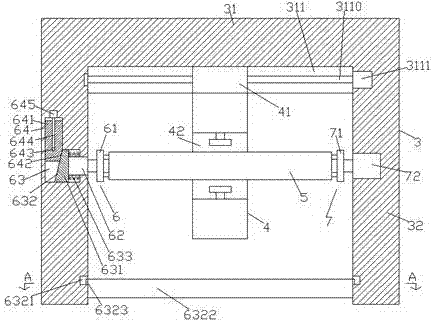
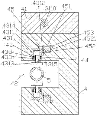
[0020] like figure 1 , figure 2 and image 3 As shown, a molding device of the present invention includes a seat body 3 composed of a push rod 31 and a machine column 32 fixed at the bottom of the left and right sides of the push rod 31. Groove 311, described sliding groove 311 is provided with the first screw rod 3110 that extends left and right to arrange, and described first screw rod 3110 is connected with moving slider 41, and the bottom of described moving slider 41 is provided with processing device 4, so The front end of the processing device 4 is provided with an operating groove 42, and the processing device 4 on the upper and lower sides of the operating groove 42 is respectively provided with a first sliding chamber 43, and the first sliding chamber 43 is separated from the operating chamber. One side of the groove 42 is provided with a second sliding chamber 45 extended to the right and communicated with each other. The second sliding chamber 45 is provided wit...


PUM


Abstract

The invention discloses a forming device. The forming device comprises a base body composed of a top rod and machine columns fixed at the bottoms of the left side and the right side of the top rod. A sliding chute is formed in the end surface of the bottom of the top rod and is provided with a first screw rod which is arranged in a left-right extension mode; a sliding block is connected in the first screw rod in a matched mode, a machining device is arranged at the bottom of the sliding block, and an operation groove is formed in the front end of the machining device; first sliding cavities are formed in the positions, on the upper side and the lower side of the operation groove, of the machining device, and second sliding cavities extending rightwards are formed in the sides, away from the operation groove, of the first sliding cavities and communicate with the first sliding cavities; second screws arranged in a left-right extension mode are arranged inside the second sliding cavities and are connected to pushing slide blocks in a matched mode; and sliding limiting blocks are arranged on the sides, adjacent to the operation groove, of the inner walls of the right side of the first sliding cavities, and vertical sliding blocks are connected in the first sliding cavities in a sliding and matched mode. The forming device is simple in structure, convenient to assemble and disassemble, high in machining efficiency and capable of meeting the requirements of machining steel columns with different diameters.

Description

technical field [0001] The invention relates to the technical field of machining, in particular to a molding device. Background technique [0002] After the steel column is poured, the surface needs to be further processed to make the surface smooth and shaped, so as to meet the application needs of high-precision industries. The existing manual processing technology is inefficient, time-consuming and labor-intensive, and has poor precision. The processing currently on the market The device is bulky and expensive, and usually has only one operating head, so the efficiency is low. Contents of the invention [0003] The technical problem to be solved by the present invention is to provide a molding device that can solve the above-mentioned problems in the prior art. [0004] The present invention is achieved through the following technical proposals: a forming device of the present invention includes a seat body composed of a push rod and a machine column fixed at the botto...

Claims


Application Information

Patent Timeline
Patent Type & Authority Applications(China)
IPC IPC(8): B23Q1/30B23Q5/40B23Q3/06B23Q39/00
CPCB23Q1/30B23Q3/06B23Q5/40B23Q39/00B23Q2039/006
Inventor 蔡玉君
Owner TAIZHOU CHIJUN INTELLIGENT EQUIP CO LTD
Why Eureka
Try Eureka