
A device and method for large-aperture collimation wavefront error detection with real-time compensation

A real-time compensation and wavefront error technology, applied in the field of optical detection, can solve the problems of inability to compensate system errors in real time, reduce system measurement accuracy, and reduce measurement accuracy, and achieve real-time system errors, improve measurement accuracy, and avoid system errors. Effect

Active Publication Date: 2019-03-01
XIAN TECH UNIV
View PDF2 Cites 0 Cited by
  • Summary
  • Abstract
  • Description
  • Claims
  • Application Information

AI Technical Summary

Problems solved by technology

However, in the actual measurement, due to the influence of air disturbance and environmental vibration, the pentaprism will inevitably vibrate when it moves, and the relative position between the wavefront of the collimated light to be measured and the guide rail will change, thereby introducing systematic errors. Reduced measurement accuracy
Patent ZL201120352084.7 uses a single scanning pentaprism to measure a large-diameter collimated light beam, and uses the invariance of the one-dimensional rotation angle of the pentaprism to convert the vertical focus during the collimation process into horizontal focus. The device structure is simple and the cost is relatively low. Low, but it is easily affected by environmental vibration and air disturbance in practical applications, so that there is a change in the relative position between the measured collimated wavefront and the guide rail, which introduces system errors and greatly reduces the measurement accuracy of the system
The existing technology (ZL201520149260.5) is a collimated beam detection technology based on double pentaprisms. Its main purpose is to measure wavefront errors and effectively compensate system errors. The systematic error of the straight beam wavefront in the case of vibration errors in all directions of the guide rail

Method used


Image

  • A device and method for large-aperture collimation wavefront error detection with real-time compensation
  • A device and method for large-aperture collimation wavefront error detection with real-time compensation
  • A device and method for large-aperture collimation wavefront error detection with real-time compensation

Examples


Embodiment Construction

[0029] The present invention will be further described below in conjunction with accompanying drawing and example.

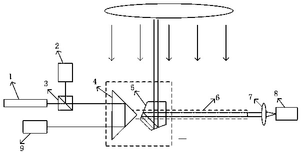
[0030] see figure 1 , a large aperture collimation wavefront error detection device with real-time compensation, comprising a beam sampling sub-device, a beam receiving sub-device and a beam compensating sub-device.

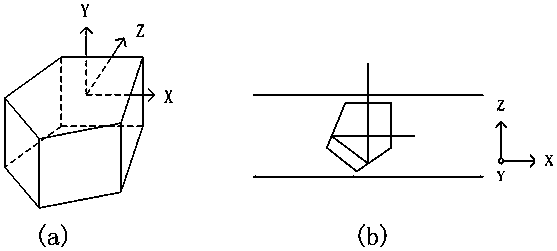
[0031] Said beam sampling sub-device consists of a pentaprism 5, a linear guide 6 and a second CCD8.

[0032] Said light beam compensating sub-device is made up of laser 1, beam splitter 3, the first CCD 2, right-angle prism 4 and the 3rd CCD9, and described beam splitter 3 is positioned at the emitting light path of laser 1, and the beam splitting surface of beam splitter 3 and light The axis forms an angle of 45 degrees, and the slope of the right-angle prism 4 is coated with a semi-transparent and semi-reflective film. The right-angle surface of the right-angle prism 4 is arranged perpendicular to the linear guide rail, and the right-angle surf...


PUM


Abstract

The present invention relates to a real-time compensation type large-aperture collimation wave front error detection device. The device comprises a light beam sampling sub-device and a light beam receiving sub-device. The light beam sampling sub-device is composed of a pentaprism, a linear guide rail and a second CCD. The device also comprises a light beam compensation sub-device. The light beam compensation sub-device consists of a laser device, a light splitting prism, a first CCD, a right-angle prism and a third CCD. The invention also discloses a real-time compensation type large-aperture collimation wave front error detection method. Based on the detection method, the system error of a to-be-detected collimated light beam under different vibration states of guide rails can be compensated in real time. The occurrence of system errors, caused by the influence of the air disturbance and the environmental vibration on linear guide rails, can be avoided. Meanwhile, the measurement method is simple in operation and high in measurement accuracy.

Description

technical field [0001] The invention relates to the technical field of optical detection, in particular to a large-aperture collimation wavefront error detection device with real-time compensation. Background technique [0002] With the wide application of large-aperture optical systems in scientific research fields such as military reconnaissance, civil resource census, astronomical optics, and space optics, as well as the progress in the processing and manufacturing of large-aperture optical components, large-aperture optical systems have been improved. Technical goals such as resolution, light-gathering ability, signal-to-noise ratio, and increased field of view. [0003] For the wavefront detection of large-aperture optical systems, the commonly used methods at home and abroad include the Shack-Hartmann method, the Talbot interferometry, the self-collimating collimator method, and the pentaprism method. [0004] The pentaprism detection method was proposed by Cui Yanmei...

Claims


Application Information

Patent Timeline
Patent Type & Authority Patents(China)
IPC IPC(8): G01J9/00
CPCG01J9/00
Inventor 朱学亮田爱玲张佳莹王红军刘丙才王春慧
Owner XIAN TECH UNIV
Learn More