
Wheel transmission mechanical lock cylinder and dragon holding cylinder type key

A technology of mechanical lock cylinder and dragon holding post, which is applied in the field of locks, can solve the problems of dependence on electricity, fragile life of electronic components, poor safety, etc., and achieve the effect of increasing the position difference distance

Active Publication Date: 2017-08-04
滁州锁神智能科技有限公司
View PDF4 Cites 2 Cited by
  • Summary
  • Abstract
  • Description
  • Claims
  • Application Information

AI Technical Summary

Problems solved by technology

Because the traditional mechanical lock cylinder has congenital defects, new locks such as electronic, photoelectric, magnetic and mechanical combination locks have emerged at the historic moment, but these new locks also have their congenital defects, for example, they are expensive, occupy a large space (large ), electronic components are fragile (short life), rely on electricity, some electronic and electromagnetic locks are easy to crack, such as magnetic card locks, fingerprint locks, remote control locks, etc. For these reasons, modern new locks are difficult to popularize
However, the traditional mechanical locks are less secure and can even open the lock in seconds
The existing traditional mechanical lock cylinder basically controls whether the lock cylinder can be opened or not through the pin or blade brake dial or the deadbolt. No matter how you improve it, you can't change its congenital defect, that is, the pin or leaf that controls whether the lock cylinder can be opened has a small "position difference distance", which is within a few millimeters, so it is easy to open without a key. Super class B and C locks are also easy to open without a key, even by a light impact in seconds

Method used


Image

  • Wheel transmission mechanical lock cylinder and dragon holding cylinder type key
  • Wheel transmission mechanical lock cylinder and dragon holding cylinder type key

Examples


Embodiment Construction

[0020] Here is an example of the outer door anti-theft lock core to illustrate the specific implementation

[0021] 1. For figure 1 , Insert the cylindrical part of the control rod (13) into the hollow part of the cylinder where the key body (11) and the key handle (12) are connected. The cylindrical part of the control rod (13) has a mouth (15), which can bite figure 2 The head of the middle brake lever (41), the control lever (13) can rotate freely in the position of the control lever groove (131), the push button (14) is installed in the position of the push button groove (141), and can be in the push button groove (141) slide freely, push the push button (14) to squeeze the bar of the control rod (13), turn the cylindrical part of the control rod (13), and insert the key, figure 2 Insert the head of the middle brake lever (41) into the mouth (15) of the control rod (13), and bite by the mouth (15) of the control rod figure 2 The head of the middle brake lever (41) drives...


PUM


Abstract

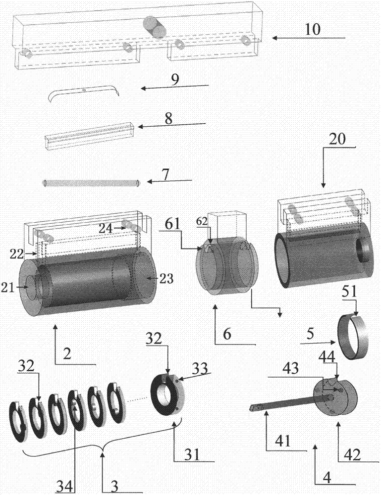
The invention discloses a wheel transmission mechanical lock cylinder and a dragon holding cylinder type key, belongs to keys, is suitable for various locks, eradicates the geneogenous defect of the displacement distance of several millimeters of a traditional mechanical lock cylinder, prevents technical unlocking and violent unlocking, and retains the advantages of the traditional mechanical lock cylinder. A dragon like guide rail or guide rail groove on a key body is held on a hollow cylinder; when a key is pushed in, a set of thinner annular transmission wheels in the lock cylinder slides on the guide rail or the guide rail groove, and rotates around the cylinder at the same time, so that the displacement distance is increased to reach several centimeters; after the key is inserted in, a brake wheel is rotated by a push button on a key handle; concave and convex parts on the brake wheel are used for extruding all the wheels, so that all the wheels form a whole; at this time, a transmission rod is fed in a transmission rod groove under the effect of a spring piece; the key is rotated to drive the transmission wheels to push the transmission rod; a poking bolt is rotated to poke a lock tongue to achieve the unlocking purpose; and when the key is pulled out, the wheels are firstly loosened, and then, the key is pulled out.

Description

Technical field [0001] The present invention belongs to the field of locks, specifically, it is a major technical improvement of the existing mechanical lock cylinder, that is, a new technology of the mechanical lock cylinder. Background technique [0002] According to the components that activate the bolt, locks are divided into electronic, photoelectric, magnetic, and mechanical locks (including mechanical code locks and traditional mechanical locks). Because traditional mechanical lock cylinders have congenital defects, new types of locks such as electronic, photoelectric, magnetic, and mechanical combination locks have emerged, but these new locks also have their congenital defects, such as expensive and large space (large volume) ), electronic components are fragile (short life) and rely on electricity. Some electronic and electromagnetic locks are easy to crack, such as magnetic card locks, fingerprint locks, remote control locks, etc. For these reasons, modern new locks ar...

Claims


Application Information

Patent Timeline
IPC IPC(8): E05B19/00E05B35/00E05B35/14
CPCE05B19/00E05B19/0017E05B35/00E05B35/14
Inventor 郑志文
Owner 滁州锁神智能科技有限公司
Learn More