Eureka AIR delivers breakthrough ideas for toughest innovation challenges, trusted by R&D personnel around the world.

Interior magnet rotary electric machine

A technology of rotating electrical machines and magnets, applied to synchronous motors with stationary armatures and rotating magnets, magnetic circuit rotating parts, magnetic circuits, etc. Achieve high-speed rotation efficiency, suppress eddy current loss, and improve strength

Active Publication Date: 2017-08-01
KOBE STEEL LTD
View PDF7 Cites 0 Cited by
  • Summary
  • Abstract
  • Description
  • Claims
  • Application Information

AI Technical Summary

Problems solved by technology

Among them, the process of winding fiber-reinforced metal wires for each rotor requires many man-hours (time), and the production of equipment and jigs is expensive.

Method used


Image

  • Interior magnet rotary electric machine
  • Interior magnet rotary electric machine
  • Interior magnet rotary electric machine

Examples


no. 1 approach

[0028] (Structure of IPM motor)

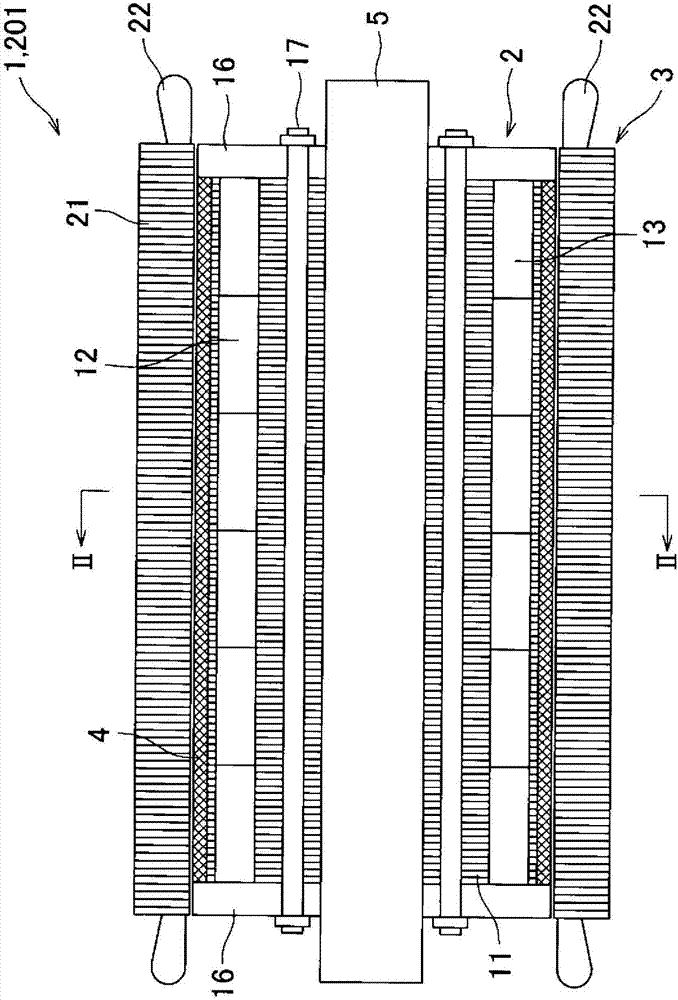
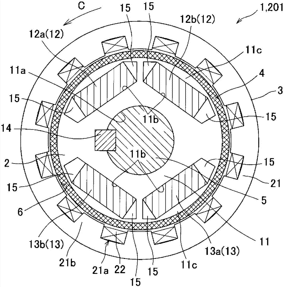
[0029] A magnet-embedded rotating electrical machine according to a first embodiment of the present invention is an IPM motor. as a sectional view figure 1 and as figure 1 Line II-II sectional view of figure 2 As shown, the IPM motor 1 has a rotor (rotator) 2 and a cylindrical stator (fixer) 3 arranged to face the rotor 2 on the radially outer side of the rotor 2 . The rotor 2 is disposed within the stator 3 so that its axis coincides with that of the stator 3 (coaxially). In addition, the rotor 2 and the stator 3 are housed in an unillustrated case.

[0030] (rotor)

[0031] The rotor 2 has a cylindrical rotor core 11 and two sets of permanent magnets 12 and 13 embedded in the rotor core 11 . Rotor 2 is able to figure 2 The C direction shown and its opposite direction of rotation.

[0032] The rotor core 11 is formed, for example, by laminating annular plate-shaped electrical steel sheets (35H300 or the like) in the axial direction....


PUM


Abstract

The invention provides an interior magnet rotary electric machine. This interior magnet rotary electric machine (1) is provided with a rotor (2) that has a rotor core (11) having two sets of permanent magnets (12, 13) embedded therein, a stator (3) that is disposed facing the rotor (2), and a fiber strengthened plastic tube (4) which sleeves and is fixed at the rotor core (11).

Description

technical field [0001] The present invention relates to a magnet-embedded rotating electrical machine including a rotor having a rotor core in which permanent magnets are embedded, and a stator arranged to face the rotor. Background technique [0002] Rotating electrical machines are the general term for electric motors, generators, motors and generators. When the magnet-embedded rotating electric machine of the present invention is used as an electric motor, the electric motor is called an IPM (Interior Permanent Magnet) motor. In contrast, a motor having a rotor in which permanent magnets are attached to the surface of a rotor core is called an SPM (Surface Permanent Magnet) motor. In addition, the IPM motor and the SPM motor are collectively referred to as a PM motor. [0003] The ultimate goal of the present invention is to achieve high-speed rotation of the IPM motor. As an invention related to the SPM motor rather than the IPM motor, but the subject is to solve the ...

Claims


Application Information

Patent Timeline
Patent Type & Authority Applications(China)
IPC IPC(8): H02K1/27
CPCH02K1/276H02K1/28H02K21/14
Inventor 下田敏章笠井信吾
Owner KOBE STEEL LTD
Why Eureka
Eureka Blog
Learn More