
Ground leakage drain pipe structure and manufacture method thereof

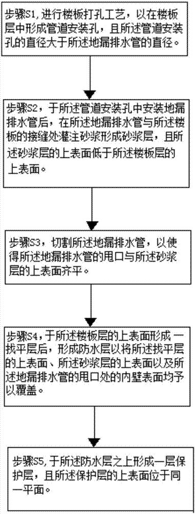
A production method and technology for drainage pipes, which are applied in drainage structures, sewer pipe systems, waterway systems, etc., can solve problems such as easy water leakage, and achieve the effect of reducing the probability of water leakage.

Inactive Publication Date: 2017-08-01
MCC5 GROUP CORP SHANGHAI
View PDF5 Cites 2 Cited by
  • Summary
  • Abstract
  • Description
  • Claims
  • Application Information

AI Technical Summary

Problems solved by technology

The general practice is that the opening of the drainpipe is flush with the protective layer. In this way, it is easy to form hidden water on the waterproof layer, and then it is easy to cause water leakage. This is what those skilled in the art do not expect to see

Method used


Image

  • Ground leakage drain pipe structure and manufacture method thereof
  • Ground leakage drain pipe structure and manufacture method thereof

Examples


Embodiment Construction

[0028] The present invention will be further described below in conjunction with the accompanying drawings and specific embodiments, but not as a limitation of the present invention.

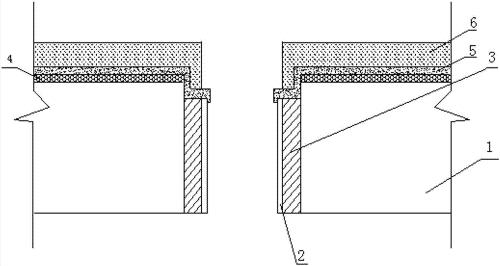
[0029] Such as figure 1 As shown, the present invention discloses a floor drain drain pipe 2 structure, which is applied to toilets. Specifically, the floor drain drain pipe 2 structure includes a floor layer 1, a floor drain drain pipe 2, a mortar layer 3, and a leveling layer 4. The waterproof layer 5 and the protective layer 6; specifically, a pipe installation hole is formed in the floor layer 1; the floor drain drain pipe 2 is arranged in the pipe installation hole, and the opening of the floor drain drain pipe 2 is lower than that of the floor layer 1. The upper surface; the mortar layer 3 is arranged at the joint between the floor drain pipe 2 and the floor layer 1, and fills the joint between the floor drain pipe 2 and the floor layer 1; the leveling layer 4 is arranged on the floor laye...


PUM


Abstract

The invention relates to the technical field of ornament and decoration, in particular to a ground leakage drain pipe structure and a manufacture method thereof. By enabling the reserved connector position of a ground leakage drain pipe to be lower than the upper surface of a floor slab layer so as to form a ladder groove between the ground leakage drain pipe and the floor slab layer, leaked water can flow in a drain pipe through the ladder groove, and then water hidden on a waterproof layer is convenient for draining accordingly, thereby reducing the water leaking probability.

Description

technical field [0001] The invention relates to the technical field of decoration, in particular to a floor drain drainage pipe structure and a manufacturing method thereof. Background technique [0002] At present, when the floor drain drain pipe is installed at the construction site, the floor drain drain pipe mostly exceeds the surface of the cast-in-place floor slab. The general practice is that the opening of the drainpipe is flush with the protective layer. In this way, it is easy to form hidden water accumulation on the waterproof layer, and then water leakage is easy to occur. This is what those skilled in the art do not expect to see. Contents of the invention [0003] In view of the above existing problems, the present invention discloses a floor drain drainage pipe structure, which includes: [0004] a floor layer, wherein a pipe installation hole is formed in the floor layer; [0005] The drain pipe of the floor drain is arranged in the pipe installation hole...

Claims


Application Information

Patent Timeline
Patent Type & Authority Applications(China)
IPC IPC(8): E03F5/04E03F3/02E03F3/06
Inventor 杨维华
Owner MCC5 GROUP CORP SHANGHAI
Learn More